
Page 236 - High Temperature Solid Oxide Fuel Cells Fundamentals, Design and Applications
P. 236
Cell and Stack Designs 2 13
Ni/YSZ slurry over the electrolyte followed by sintering has also yielded anodes
that are equivalent in performance to those fabricated by the EVD process.
Deposition of the anode by a thermal spraying method is also being investigated.
Use of these non-EVD processes should result in a substantial reduction in the
cost of manufacturing SOFCs.
Doped lanthanum chromite interconnection is deposited in the form of about
85 pm thick, 9 mm wide strip along the air electrode tube length by plasma
spraying followed by densification sintering [29].
8.3.1 Cell Operation and Performance
The cell tube is closed at one end. For cell operation, oxidant (air or oxygen) is
introduced through an alumina injector tube positioned inside the cell. The
oxidant is discharged near the closed end of the cell and flows through the
annular space formed by the cell and the coaxial injector tube. Fuel flows on the
outside of the cell from the closed end and is electrochemically oxidised while
flowing to the open end of the cell generating electricity. At the open end of the
cell, the oxygen-depleted air exits the cell and is combusted with the partially
depleted fuel. Typically, 50-90% of the fuel is utilised in the electrochemical cell
reaction. Part of the depleted fuel is recirculated in the fuel stream and the rest
combusted to preheat incoming air and/or fuel. The exhaust gas from the fuel
cell is at 600-900°C depending on the operating conditions.
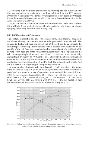
A large number of tubular cells have been electrically tested over the years,
some for times as long as 8 years. These cells perform satisfactorily for extended
periods of time under a variety of operating conditions with less than 0.1% per
1000 h performance degradation. The voltage-current and power-current
characteristics of a commercial prototypic 2.2 cm diameter, 150 cm active
length cell at 900, 940, and 1000°C with 89% H2 + 11% H20 fuel (85% fuel
utilisation) and air as oxidant (4 stoichs) are shown in Figure 8.16.
0 900 275
0 850 250
0 800 225
200
0 750
0 7W
m
0650
-
” 0600
100 8 H.
0 550
75
0 5W
50
0 450 25
0 4W 0
0 50 100 150 200 250 300 350 400 450 500 550
Cumnl Density (mNcm*)
Figure 8. I6 Voltage-current density andpower-current densityplots of a commercialprototypical tubular
SOFC. (Courtesy o1Siemens Westinghouse Power Corporation.)