
Page 241 - High Temperature Solid Oxide Fuel Cells Fundamentals, Design and Applications
P. 241
2 18 High Tewiperature Solid Oxide Fuel Crlls: Fundamentals, Design and Applications
has closed ends similar to the tubular design that provide integral air return
paths for air to flow the entire length of the cell from the closed to the open end.
The HPD-SOFC departs from the tubular design in that it is flattened and
incorporates a number of ribs in the air electrode that act as bridges for current
flow. Figure 8.23 compares the cross-sections ofthe tubular and the HPD-SOFCs.
The ribs reduce the current path length, which in turn reduces the internal
Figure 8.23 Cross-sections oJtubularandjattened ribbedHPDcells [37].
resistance of the cell. The presence of the ribs, due to the decreased internal
resistance of the cell, also allows use of thinner air electrodes which reduces the
air electrode polarisation (a thicker air electrode results in a higher diffusion path
for oxygen from the gas phase to the air electrode/electrolyte interface resulting
in higher polarisation). The ribs also form air channels that eliminate the need
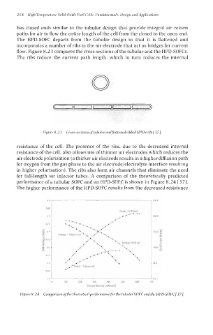
for full-length air injector tubes. A comparison of the theoretically predicted
performance of a tubular SOFC and an HPD-SOFC is shown in Figure 8.24 [37].
The higher performance of the HPD-SOFC results from the decreased resistance
09 250 0
0 85
Power-HPDcell
08 200 0
- 0 75 -
Y)
g 07 1500
2 E
- tl
a,
p 065
-
2 5
1 06 1000
0
0 55
05 50 0
0 45
04 00
0 100 200 300 4w 500 600 700
Current Density [mAicmS]
Figure 8.24 Comparison of the theoreticalperformance for the tubular SOFC and the HPD-SOFC[37].