
Page 243 - High Temperature Solid Oxide Fuel Cells Fundamentals, Design and Applications
P. 243
220 High Temperature Solid Oxide Fuel Cells: Fundamentals, Design and Applications
the tube to a thickness of around 50 pm, and a nickel current collector wire is
inserted and brought out from the fuel entry side of the tube. On the outside of the
electrolyte tube, the lanthanum strontium manganite cathode layer, some 100
pm thick, is deposited, fired, and a silver wire is wound around it to obtain the
cathode current. Figure 8.25b shows a cross-section of the cell region on the
tube, illustrating the electrolyte support tube, the inner anode and nickel wire,
and the outer cathode and its silver wire connector. Cell interconnection is made
away from the cells in this design, so that a single interconnect material is not
necessary: however, applying the anode and its current collector down inside a
narrow tube is not trivial.
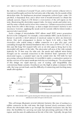
Such a design of microtubular SOFC allows small SOFC power generation
devices to be configured. For example, a microtubular SOFC can be heated in a
burner to provide a small amount of electrical output to drive an electronic
device. One such arrangement is shown in Figure 8.26 with a long YSZ
electrolyte tube sealed using a rubber connector to a gas inlet pipe, and
extending through the thermal insulation into a hot zone at 800°C [41-441. In
this case the long YSZ support tube acts as an inlet pipe to bring fuel to the
electroded cell region of the tube. The electroded cell area of the tube extends
typically for 30 mm near the tube exit, the anode and cathode wires being
brought out for external connection to the electrical load. Upstream of the
electroded region, a catalyst layer can be coated onto the YSZ tube for fuel
processing, whereas downstream, it is possible to apply a combustion catalyst to
aid the reaction of the spent anode gas with the surrounding air. The advantages
of this design are rapid start-up, ease of sealing, and integrability into
conventional flame systems. Drawbacks are the high in-plane resistance of the
cells, the long current leads, and the difficulty of connecting and stacking many
small cells together.
rubber seal I I /I
=b hot exhaust
fuel ,A
plus ectrolyte t ' uoes n
air cold Lone hot Lone
insulation
Figure 8.26 Microtubular SOFC system showing the YSZ electrolyte tube sealed with a rubber connector,
with theelectrodedcell regionin the hot zone.
This cell design illustrates several inherent features; the ease of sealing to a
rubber connector in the cold zone, the high thermal shock resistance which
allows the electrolyte tube to go through the thermal insulation into the hot
zone, the feasibility for carrying out some fuel processing upstream of the cell
region, and the ease of combustion at the exit of the tube. Typically, the gas feed