
Page 242 - High Temperature Solid Oxide Fuel Cells Fundamentals, Design and Applications
P. 242
Cell and Stack Designs 2 19
of the cells compared to the tubular SOFC. When fully optimised with respect to
the number of ribs and the resulting performance, such HPD-SOFCs are expected
to be initially used in 5 kW residential power systems mentioned in Chapter 13.
8.4 Microtubular SOFC Design
The earliest reports of work on microtubular SOFCs were in the early 1990s
when the possibility of extruding thin-walled YSZ electrolyte tubes, 1-5 mm in
diameter and between 100 and 200 pm wall thickness, was demonstrated [38],
and the ionic conductivity and leak tightness of such electrolyte tubes were
found to be good [39, 401. There are two major benefits of microtubular SOFCs.
The first is the increase in volumetric power density when compared with the
large-diameter tubular designs discussed in Section 8.3. Power density scales
with the reciprocal of tube diameter. Therefore a 2 mm diameter microtubular
SOFC could provide ten times more power per stack volume than a 20 mm
diameter tubular cell. Another order of magnitude increase could be achieved by
going to 0.2 mm diameter tubes, but this is difficult because the connections are
then more numerous and problematic to apply. The most significant issue in
microtubular cells is applying the electrode and connecting the metal contact
inside the bore of a very small-diameter tube.
The second major benefit of the microtubular design is a high thermal shock
resistance [41]. Whereas the large-diameter tubular SOFCs are prone to cracking
if they are rapidly heated, the microtubular SOFCs do not crack even when
heated in a blow torch to their operating temperature of about 850°C in as little
as 5 s. This is a marked advantage in applications where start-up time is critical.
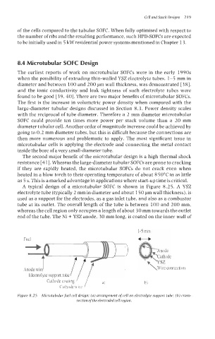
A typical design of a microtubular SOFC is shown in Figure 8.25. A YSZ
electrolyte tube (typically 2 mm in diameter and about 150 pm wall thickness), is
used as a support for the electrodes, as a gas inlet tube, and also as a combustor
tube at its outlet. The overall length of the tube is between 100 and 200 mm,
whereas the cell region only occupies a length of about 30 mm towards the outlet
end of the tube. The Ni + YSZ anode, 30 mm long, is coated on the inner wall of
1-5 mm
Fuel
Electrolyte support tube
Cathode coating b)
Cathode wire
Figure 8.25 Microtubular fuel cell design: (a) arrangement of cell on electrolyte support tube: (b) cross-
section ofthe electroded cell region.