
Page 245 - High Temperature Solid Oxide Fuel Cells Fundamentals, Design and Applications
P. 245
222 High Temperature Solid Oxide Fuel CelIs: Fundamentals, Design and Applications
T
coextruded
\
3mm
1
Cell on a co-extruded I
>
3
-
M
d 0.5
0
>
Cell on a 02 mm
thick YSZ tube
i
0 0.2 0.4 0.6 0.8 1.0
Current, A
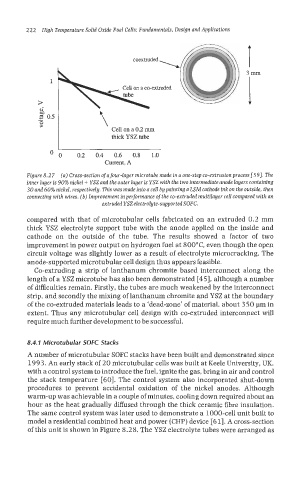
Figure 8.27 (a) Cross-section of a four-layer microtube made in a one-step co-extrusion process [59]. The
inner layer is 90% nickel + YSZ and the outer layer is YSZ with the two intermediate anode layers containing
30 and 60% nickel, respectively. This was made into a cell by painting a LSM cathode ink on the outside, then
connecting with wires. (6) lmprovement in performance of the co-extruded multilayer cell compared with an
extruded YSZ electrolyte-supported SOFC.
compared with that of microtubular cells fabricated on an extruded 0.2 mm
thick YSZ electrolyte support tube with the anode applied on the inside and
cathode on the outside of the tube. The results showed a factor of two
improvement in power output on hydrogen fuel at 8OO0C, even though the open
circuit voltage was slightly lower as a result of electrolyte microcracking. The
anode-supported microtubular cell design thus appears feasible.
Co-extruding a strip of lanthanum chromite based interconnect along the
length of a YSZ microtube has also been demonstrated [45], although a number
of difficulties remain. Firstly, the tubes are much weakened by the interconnect
strip, and secondly the mixing of lanthanum chromite and YSZ at the boundary
of the co-extruded materials leads to a ‘dead-zone’ of material, about 3 50 pm in
extent. Thus any microtubular cell design with co-extruded interconnect will
require much further development to be successful.
8.4.7 Microtubular SOFC Stacks
A number of microtubular SOFC stacks have been built and demonstrated since
1993. An early stack of 20 microtubular cells was built at Keele University, UK,
with a control system to introduce the fuel, ignite the gas, bring in air and control
the stack temperature [60]. The control system also incorporated shut-down
procedures to prevent accidental oxidation of the nickel anodes. Although
warm-up was achievable in a couple of minutes, cooling down required about an
hour as the heat gradually diffused through the thick ceramic fibre insulation.
The same control system was later used to demonstrate a 1000-cell unit built to
model a residential combined heat and power (CHP) device [61]. A cross-section
of this unit is shown in Figure 8.28. The YSZ electrolyte tubes were arranged as