
Page 88 - High Temperature Solid Oxide Fuel Cells Fundamentals, Design and Applications
P. 88
Thermodynamics 65
The number of electrons np' depends on the fuel (2 for H2), the Faraday
constant F is a constant value and the fuel inlet flow is the only variable that
influences the relation between fuel utilisation Ufand current I. Any curve of the
voltage V depending on the current 1 can be expressed by any curve of V
depending on the fuel utilisation UJat the same fuel inlet flow.
Considering Eqs. (50) and (27) we see that V + + 00 for U, + 0 and V + -ca
for U,+ 1 respectively. But the model of the ideal gas gives a good approximation
for 0 < Uf < 1 in the regime of the real SOFC operation. This model allows one to
evaluate the principal influences of the different parameters, system pressure p,
SOFC temperature €ISOFC, excess air h and fuel utilisation U,, on the Nernst
voltage VN.
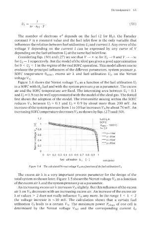
Figure 3.4 shows the Nernst voltage VN as a function of the fuel utilisation Uf
in a SOFC with H2 fuel and with the system pressurep as a parameter. The excess
air and the SOFC temperature are fixed. The interesting area between U, = 0.1
and U,= 0.9 can be well approximated with the model of the ideal gas. The dotted
line shows the adoption of the model. The irreversible mixing within the SOFC
reduces VN between U, = 0.1 and Uf = 0.9 by about more than 200 mV. An
increase of the system pressure from 1 to 10 bar increases VN by about 70 mV. An
increasing SOFC temperature decreases VN as shown by Eqs. (2 7) and (50).
fuel H, in
SOFC
6,,, = 1 ooooc
h= 2,o
-p= 1 bar
+p=2bar
4
~+ bar
p
=
1- p = 8 bar1
0 0,l 0,2 0,3 0,4 0,5 0,6 0,7 0,8 0,9 1
fuel utilisation U, [ -1 calculated
Figure 3.4 ThecalculatedNernst voltugeVNasafunctionofthefuelutilisationUf.
The excess air h is a very important process parameter for the design of the
total system as shown later. Figure 3.5 shows the Nernst voltage VN as a function
of the excess air h and the system pressure p as a parameter.
An increasing excess air h increases V, slightly. But this influence of the excess
air h on VN decreases with an increasing excess air. An increase of the excess air
h at values > 2 does not really influence VN any more. In the range 1 < h < 2
the voltage increase is -30 mV. The calculation shows that a certain fuel
utilisation U, leads to a certain VN-, The maximum power Pelmnx of one cell is
determined by the Nernst voltage VNo and the corresponding current Io