
Page 89 - High Temperature Solid Oxide Fuel Cells Fundamentals, Design and Applications
P. 89
66 High Temperature Solid Oxide Fuel Cells: Fundamentals, Design and Applications
> - fuel H,in
- 0,9
SOFC
fiSOFC = 1 ooooc
b 2.0
L-
Uf
- = 0,7
Uf
+ = 0.8
*Uf=O9
1 2 3 4 5 6 7 a 9 IO
system pressure p [bar]
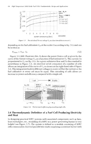
Figure 3.5 The calculated Nernst voltage VN as a Junction ofthe excess air h.
depending on the fuel utilisation U~,-J at the outlet 0 according to Eq. (5 1) and can
be written as
Pelrnax = VNO ' 10. (52)
Figure 3.6 (left) illustrates this. It shows the power from a cell as given by the
curve of the Nernst voltage VN as a function of fuel utilisation Up The current I is
proportional to U, see Eq. (5 l), for a given substance flow and I is thus marked in
parentheses in Figure 3.6. An electrical serial connection of a number of cells
allows an integration of the curve of VN as shown at the right-hand side of Figure
3.6. This integration leads to different voltages in every cell but the current or the
fuel utilisation in every cell must be equal. This cascading of cells allows an
increase in power and efficiency compared with a single cell.
Ut - Uf -
L. (1) UfO (1) UfO
Figure 3.6 The increase in efficiency by cascading single cells.
3.4 Thermodynamic Definition of a Fuel Cell Producing Electricity
and Heat
In designing practical SOFC systems with associated components such as fans,
heat exchangers, etc., modelling of a SOFC as a power generating burner is very
helpful (see Figure 3.7). The system is defined as a module consisting of SOFC
cells connected in electrical parallel into stacks supplying a common burner with