
Page 90 - High Temperature Solid Oxide Fuel Cells Fundamentals, Design and Applications
P. 90
Thermodynamics 67
balance borders
anode side An 6
\ FC 4 7 ‘el
I
cathode side Ca SOW- ++* burner
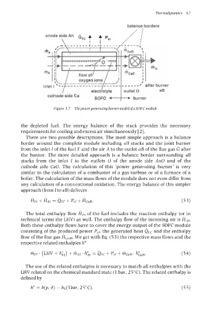
Figure 3.7 Thepower generating burner model of a SOFC module.
the depleted fuel. The energy balance of the stack provides the necessary
requirements for cooling and excess air simultaneously [2].
There are two possible descriptions. The most simple approach is a balance
border around the complete module including all stacks and the joint burner
from the inlet I of the fuel F and the air A to the outlet aB of the flue gas G after
the burner. The more detailed approach is a balance border surrounding all
stacks from the inlet I to the outlets 0 of the anode side An0 and of the
cathode side CaO. The calculation of this ‘power generating burner’ is very
similar to the calculation of a combustor of a gas turbine or of a furnace of a
boiler. The calculation of the mass flows of the module does not even differ from
any calculation of a conventional oxidation. The energy balance of this simpler
approach (from I to LIB) delivers
HFI + HAI = QFC + pel + &OB. (53)
The total enthalpy flow HF, of the fuel includes the reaction enthalpy (or in
technical terms the LHV) as well. The enthalpy flow of the incoming air is HAI.
Both these enthalpy flows have to cover the energy output of the SOFC module
consisting of the produced power Pel, the generated heat dFc and the enthalpy
flow of the flue gas HGnB. We get with Eq. (53) the respective mass flows and the
respective related enthalpies h*
= QFC + pel + GOB ’ h&~. (54)
hFI ’ (LHV + h;I) + hAI ’
The use of the related enthalpies is necessary to match all enthalpies with the
LHV related on the chemical standard state (1 bar, 25°C). The related enthalpy is
defined by
h* = h(p, 0) - ho(lbar, 25°C). (55)