Page 102 - Highway Engineering Handbook Building and Rehabilitating the Infrastructure
P. 102

HIGHWAY LOCATION, DESIGN, AND TRAFFIC           85

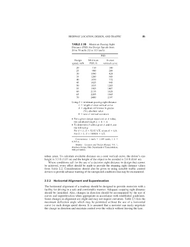
                                               TABLE 2.3B  Minimum Passing Sight
                                               Distance (PSD) for Design Speeds from
                                               20 to 70 mi/h (32 to 113 km/h)
                                                                  PSD
                                                 Design   Minimum     K-crest
                                               speed, mi/h  PSD, ft  vertical curve
                                                  20        710        180
                                                  25        900        289
                                                  30        1090       424
                                                  35        1280       585
                                                  40        1470       772
                                                  45        1625       943
                                                  50        1835      1203
                                                  55        1985      1407
                                                  60        2135      1628
                                                  65        2285      1865
                                                  70        2480      2197
                                               Using S   minimum passing sight distance
                                                    L   length of crest vertical curve
                                                    A   algebraic difference in grades
                                                       (%), absolute value
                                                   K   rate of vertical curvature
                                               ● For a given design speed and an A value,
                                                 the calculated length L   K   A.
                                               ● To determine S with a given L and A, use
                                                 the following:
                                                 For S   L: S   52.92  K  , where K   L/A.
                                                 For S   L: S   1400/A 	 L/2.
                                                  Conversions: 1 mi/h   1.609 km/h, 1 ft
                                               0.305 m.
                                                  Source: Location and Design Manual, Vol. 1,
                                               Roadway Design, Ohio Department of Transportation,
                                               with permission.
                              urban areas. To calculate available distance on a crest vertical curve, the driver’s eye
                              height is 3.5 ft (1.07 m) and the height of the object to be avoided is 2.0 ft (0.61 m).
                                Where conditions call for the use of a decision sight distance in design that cannot
                              be achieved, every effort should be made to provide the stopping sight distance values
                              from Table 2.2. Consideration should also be given to using suitable traffic control
                              devices to provide advance warning of the unexpected conditions that may be encountered.


                              2.2.3 Horizontal Alignment and Superelevation
                              The horizontal alignment of a roadway should be designed to provide motorists with a
                              facility for driving in a safe and comfortable manner. Adequate stopping sight distance
                              should be furnished. Also, changes in direction should be accompanied by the use of
                              curves and superelevation when appropriate in accordance with established guidelines.
                              Some changes in alignment are slight and may not require curvature. Table 2.5 lists the
                              maximum deflection angle which may be permitted without the use of a horizontal
                              curve for each design speed shown. It is assumed that a motorist can easily negotiate
                              the change in direction and maintain control over the vehicle without leaving the lane.
   97   98   99   100   101   102   103   104   105   106   107