
Page 100 - Hybrid-Renewable Energy Systems in Microgrids
P. 100
84 Hybrid-Renewable Energy Systems in Microgrids
1.1 Switching sequences
Switching the sequences in this converter is easier than its counter parts. According to
its inherent advantages, it does not need to generate negative pulses for negative cycle
control. So there is no need for extra conditions and driver circuits for controlling
the negative voltage. Instead, the reversing full bridge converter performs this task,
and the required level is produced by the high switching frequency component of the
inverter. Then this level is transferred to negative or positive polarity according to the
output voltage requirements.
This topology is redundant and flexible in the switching sequence. Different
switching modes in generating the required levels for a seven level RV inverter are
depicted in Table 5.1.
In Table 5.1 the numbers refer to the switches according to Fig. 5.1 which should
be turned on to generate the required voltage level. According to the table, there are
four possible switching patterns to control the inverter. It shows the great redundancy
of the topology.
In order to avoid unwanted voltage levels during switching cycles, the switching
modes should be selected so that the switching transitions become minimal during the
transfer between levels. This will also help to decrease switching power dissipation.
Therefore, the sequences of switches (2-3-4), (2-3-5), (2-6-5) and (1, 5) are chosen for
levels 0 up to 3, respectively. These sequences are shown in Fig. 5.3. As can be ob-
served from Fig. 5.3, the output voltage levels are generated in this part by appropriate
switching sequences. The ultimate output voltage level is the sum of voltage sources,
which are included in the current path that is marked in bold.
In order to produce seven levels by SPWM, three saw-tooth waveforms for carrier
and a sinusoidal reference signal for modulator are required as shown in Fig. 5.4.
In this work PD (Phase Disposition) SPWM is adopted for its simplicity [3]. Car-
riers in this method do not have any coincidence, and they have definite offset from
each other. They are also in phase with each other. The modulator and three carriers
for SPWM are depicted in Fig. 5.4.
According to Fig. 5.4, three states are considered. The first state is when the
modulator signal is within the lowest carrier. The second state is when it is within
the middle carrier. Finally, the third one is when it is within the highest carrier. In
each state certain switching cases are adopted to cover the voltage requirements. Ac-
cording to this definition, the switching states and switching modes are described in
Table 5.2.
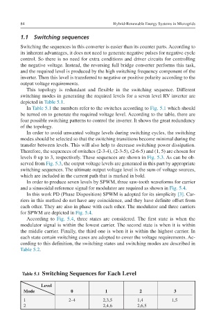
Table 5.1 Switching Sequences for Each Level
Level
Mode 0 1 2 3
1 2–4 2,3,5 1,4 1,5
2 2,4,6 2,6,5