
Page 103 - Hybrid-Renewable Energy Systems in Microgrids
P. 103
Multilevel inverters for photovoltaic energy systems in hybrid-renewable energy systems 87
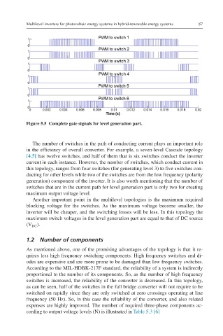
Figure 5.5 Complete gate signals for level generation part.
The number of switches in the path of conducting current plays an important role
in the efficiency of overall converter. For example, a seven-level Cascade topology
[4,5] has twelve switches, and half of them that is six switches conduct the inverter
current in each instance. However, the number of switches, which conduct current in
this topology, ranges from four switches (for generating level 3) to five switches con-
ducting for other levels while two of the switches are from the low frequency (polarity
generation) component of the inverter. It is also worth mentioning that the number of
switches that are in the current path for level generation part is only two for creating
maximum output voltage level.
Another important point in the multilevel topologies is the maximum required
blocking voltage for the switches. As the maximum voltage become smaller, the
inverter will be cheaper, and the switching losses will be less. In this topology the
maximum switch voltages in the level generation part are equal to that of DC source
(V ).
DC
1.2 Number of components
As mentioned above, one of the promising advantages of the topology is that it re-
quires less high frequency switching components. High frequency switches and di-
odes are expensive and are more prone to be damaged than low frequency switches.
According to the MIL-HDBK-217F standard, the reliability of a system is indirectly
proportional to the number of its components. So, as the number of high frequency
switches is increased, the reliability of the converter is decreased. In this topology,
as can be seen, half of the switches in the full bridge converter will not require to be
switched on rapidly since they are only switched at zero crossings operating at line
frequency (50 Hz). So, in this case the reliability of the converter, and also related
expenses are highly improved. The number of required three-phase components ac-
cording to output voltage levels (N) is illustrated in Table 5.3 [6]