
Page 105 - Hybrid-Renewable Energy Systems in Microgrids
P. 105
Multilevel inverters for photovoltaic energy systems in hybrid-renewable energy systems 89
Figure 5.7 Required switches for multi level inverter.
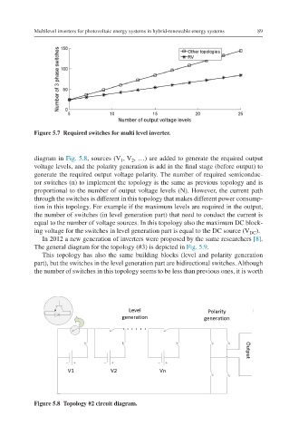
diagram in Fig. 5.8, sources (V , V , …) are added to generate the required output
1
2
voltage levels, and the polarity generation is add in the final stage (before output) to
generate the required output voltage polarity. The number of required semiconduc-
tor switches (n) to implement the topology is the same as previous topology and is
proportional to the number of output voltage levels (N). However, the current path
through the switches is different in this topology that makes different power consump-
tion in this topology. For example if the maximum levels are required in the output,
the number of switches (in level generation part) that need to conduct the current is
equal to the number of voltage sources. In this topology also the maximum DC block-
ing voltage for the switches in level generation part is equal to the DC source (V ).
DC
In 2012 a new generation of inverters were proposed by the same researchers [8].
The general diagram for the topology (#3) is depicted in Fig. 5.9.
This topology has also the same building blocks (level and polarity generation
part), but the switches in the level generation part are bidirectional switches. Although
the number of switches in this topology seems to be less than previous ones, it is worth
Figure 5.8 Topology #2 circuit diagram.