
Page 106 - Hybrid-Renewable Energy Systems in Microgrids
P. 106
90 Hybrid-Renewable Energy Systems in Microgrids
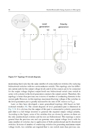
Figure 5.9 Topology #3 circuit diagram.
mentioning that it also has the same number of semiconductor switches (by replacing
bidirectional switches with two semiconductor switch). This topology also has differ-
ent current path for the output voltage levels and if all the sources are to be connected
for the output voltage (highest output level) one bidirectional switch (one switch in
series with a diode) in the level generation conducts the output current. Therefore, this
topology is better than previous one in terms of number of conducting elements in the
current path. However, in this topology maximum blocking voltage of the switches in
the level generation part is greatly increased to the sum of DC sources (n.V ).
DC
Later on they have developed a more generalized topology (#4) based on bidi-
rectional switches [9]. The circuit diagram of level generation part is illustrated in
Fig. 5.10. It is obvious that the output of this part is connected to polarity generation
part (that is a full bridge inverter) to generate the required output voltage polarity.
According to the figure, some of the switches that are shown by arrows on them are
the only unidirectional switches and the rest are bidirectional. This topology is more
general than the previous one and can generate more output voltage levels with the
same number of switches due to application of both unidirectional and bi directional
switches. In terms of number of conducting switches for generating maximum output
voltage levels, two switches are required that is one switch more than previous one.