
Page 102 - Hybrid-Renewable Energy Systems in Microgrids
P. 102
86 Hybrid-Renewable Energy Systems in Microgrids
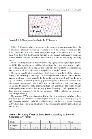
Figure 5.4 SPWM carrier and modulator for RV topology.
Table 5.2 shows the relation between the right comparator output according to the
current state and required states for switching to meet the voltage requirements. The
Right comparator, here, refers to the comparator output of the current state. As illus-
trated from Table 5.2, the transition between modes in each state requires minimum
commutation of switches to improve the efficiency of the inverter during switching
states.
These switching modes can be implemented by logic gates or digital signal proces-
sor (DSP). The signals stage should be isolated from the power stage by optocouplers
for control circuit protection. The drive circuit is also responsible to generate the dead
time between each successive switching cycle across the DC source.
The gating signal for the output stage, which changes the polarity of the voltage, is
simple. Low frequency output stage is a H- bridge inverter and works in two modes:
forward mode and reverse mode. In the forward mode, switches 8 and 9 as shown in
Fig. 5.1 conduct, and the output voltage polarity is positive. However, switches 7 and
10 conduct in reverse mode, which will lead to negative voltage polarity in the output.
So, the low frequency polarity generation stage only determines the output polarity
and is synchronous with the line frequency. Low frequency polarity generation part
drive signals are generated with the line frequency (50 Hz), and they only change at
zero voltage crossings.
The resulting PWM waveforms for driving the high frequency switches in level
generation part are illustrated for one complete cycle in Fig. 5.5. According to Fig. 5.5
high frequency switches can be adopted in this stage based on the required frequency
and voltage level. For more details about the experimental results, researchers are
referred to [1].
Table 5.2 Switching Cases in Each State According to Related
Comparator Output
States One Two Three
Compare + – + – + –
Mode 2-3-5 2-3-4 2-5-6 2-3-5 1-5 2-5-6