
Page 107 - Hybrid-Renewable Energy Systems in Microgrids
P. 107
Multilevel inverters for photovoltaic energy systems in hybrid-renewable energy systems 91
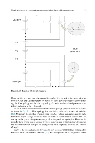
Figure 5.10 Topology #4 circuit diagram.
However, the previous one also needed to conduct the current in the same situation
from a switch and a diode that almost makes the same power dissipation as this topol-
ogy. In this topology also the blocking voltage for switches in the level generation part
is high and equal to (n − 1)V /2.
DC
In 2013, the research team introduced a new topology (#5) called cross-switched
as shown in Fig. 5.11. This topology has also led to reduce the number of switches
[10]. Moreover, the number of conducting switches in level generation part to make
maximum output voltage levels has been increased to the number of sources that will
add up to the power dissipation (compared to the previous topologies. However, its
modularity to create output voltage levels is an advantage of the topology. Moreover,
the maximum switch voltages in level generation is improved to twice DC sources
(2.V ).
DC
In 2015, the researchers also developed a new topology (#6) that has better perfor-
mance in terms of number of switches [11]. According to the circuit diagram as shown