
Page 116 - Hybrid-Renewable Energy Systems in Microgrids
P. 116
100 Hybrid-Renewable Energy Systems in Microgrids
to analyze the harmonic content [14]. The SFPLL structure is similar to the conven-
tional PQPLL structure. But, SFPLL is mainly used to three phase system in effective
synchronize between grid voltage and inverter. In these methods, the instantaneous
phase-angle has been estimated by rotating reference frame of synchronizing unit to
utility voltage vector. The PLL has fixed the dq to zero as a reference voltage. Also,
the reference is sealed to utility voltage vector in phase-angle. These methods had
been failed in the case of the presence of sub-harmonic in the grid system, which
leads to more oscillations and fails to voltage tracking during the initial condition. To
overcome this issue, the robust PQPLL has developed, which is shown in Fig. 6.4.
This method is continuously tracing the voltage and synchronized in the presence of
harmonics, negative sequence imbalance and imbalanced sub-harmonics [14].
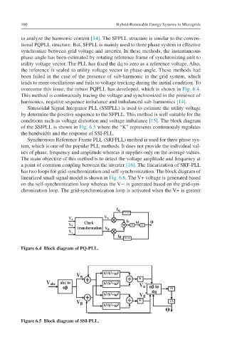
Sinusoidal Signal Integrator PLL (SSIPLL) is used to estimate the utility voltage
by determine the positive sequence to the SFPLL. This method is well suitable for the
conditions such as voltage distortion and voltage imbalance [15]. The block diagram
of the SSIPLL is shown in Fig. 6.5 where the “K” represents continuously regulates
the bandwidth and the response of SSI-PLL.
Synchronous Reference Frame PLL (SRFPLL) method is used for three phase sys-
tem, which is one of the popular PLL methods. It does not provide the individual val-
ues of phase, frequency and amplitude whereas it supplies only on the average values.
The main objective of this method is to detect the voltage amplitude and frequency at
a point of common coupling between the inverter [16]. The linearization of SRF-PLL
has two loops for grid-synchronization and self-synchronization. The block diagram of
linearized small signal model is shown in Fig. 6.6. The V+ voltage is generated based
on the self-synchronization loop whereas the V− is generated based on the grid-syn-
chronization loop. The grid-synchronization loop is activated when the V+ is greater
Figure 6.4 Block diagram of PQ-PLL.
Figure 6.5 Block diagram of SSI-PLL.