
Page 117 - Hybrid-Renewable Energy Systems in Microgrids
P. 117
An overview of control techniques and technical challenge for inverters in micro grid 101
A=x εµcosφw'=x εµsinφφ'=w+x sinw'
3
1
2
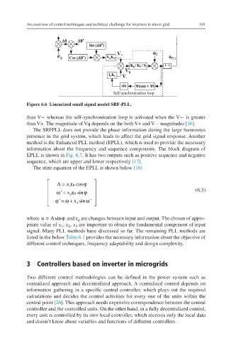
Figure 6.6 Linearized small signal model SRF-PLL.
than V− whereas the self-synchronization loop is activated when the V− is greater
than V+. The magnitude of Vq depends on the both V+ and V− magnitudes [16].
The SRFPLL does not provide the phase information during the large harmonics
presence in the grid system, which leads to affect the grid signal response. Another
method is the Enhanced PLL method (EPLL), which is used to provide the necessary
information about the frequency and sequence components. The block diagram of
EPLL is shown in Fig. 6.7. It has two outputs such as positive sequence and negative
sequence, which are upper and lower respectively [17].
The state equation of the EPLL is shown below [16]
A = x εµ cos ϕ
1 (6.3)
ω= x 2 εµ sin ϕ
'
ω
'
ϕ= ω+ x sin'
3
where =u Asin ϕ and ε are changes between input and output. The chosen of appro- u=Asinφ
µ
priate value of x , x , x are important to obtain the fundamental component of input
2
3
1
signal. Many PLL methods have discussed so far. The remaining PLL methods are
listed in the below Table 6.1 provides the necessary information about the objective of
different control techniques, frequency adaptability and design complexity.
3 Controllers based on inverter in microgrids
Two different control methodologies can be defined in the power system such as
centralized approach and decentralized approach. A centralized control depends on
information gathering in a specific central controller, which plays out the required
calculations and decides the control activities for every one of the units within the
central point [26]. This approach needs expensive correspondence between the central
controller and the controlled units. On the other hand, in a fully decentralized control,
every unit is controlled by its own local controller, which receives only the local data
and doesn’t know about variables and functions of different controllers.