
Page 115 - Hybrid-Renewable Energy Systems in Microgrids
P. 115
An overview of control techniques and technical challenge for inverters in micro grid 99
angle difference between inverter-grid voltages also the reactive power is controlled
by regulating the amplitude of the generated voltage and grid voltage [11]. The expres-
sion for sharing the real and reactive power between the DG converter voltage and grid
voltage as shown below [12]
VE
P = grid gen sin θ −θ (6.1)
Q=VgridXsEgencosθgen−θg
X gen grid P=VgridEgenXssinθgen−θgrid
s
rid−Vgrid
V
Q = grid E cos (θ −θ ) − V (6.2)
X s gen gen grid grid
where V grid and E gen represents the grid voltage and generator terminal voltage respec-
tively, (θ gen − θ grid ) represents the phase angle difference between generator voltage θgen−θgrid
and grid, X s represents the line impedance between connection of grid source and
synchronous generator.
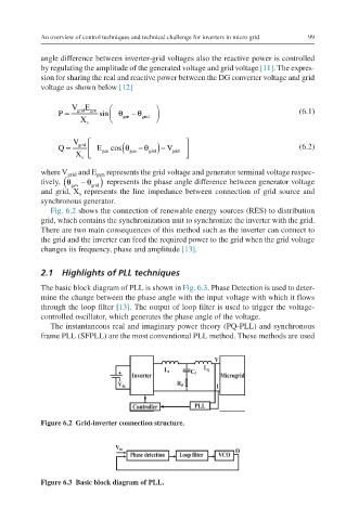
Fig. 6.2 shows the connection of renewable energy sources (RES) to distribution
grid, which contains the synchronization unit to synchronize the inverter with the grid.
There are two main consequences of this method such as the inverter can connect to
the grid and the inverter can feed the required power to the grid when the grid voltage
changes its frequency, phase and amplitude [13].
2.1 Highlights of PLL techniques
The basic block diagram of PLL is shown in Fig. 6.3. Phase Detection is used to deter-
mine the change between the phase angle with the input voltage with which it flows
through the loop filter [13]. The output of loop filter is used to trigger the voltage-
controlled oscillator, which generates the phase angle of the voltage.
The instantaneous real and imaginary power theory (PQ-PLL) and synchronous
frame PLL (SFPLL) are the most conventional PLL method. These methods are used
Figure 6.2 Grid-inverter connection structure.
Figure 6.3 Basic block diagram of PLL.