
Page 151 - Hybrid-Renewable Energy Systems in Microgrids
P. 151
Study of control strategies of power electronics during faults in microgrids 135
ref
ref
where f and V are the frequency and voltage amplitude references for the volt-
age control loop; while m and n are the slops of the droop characteristics; P meas and
Q meas denote the measured active and reactive power delivered by the converter. In
Fig. 7.9C, virtual impedance is used to modify the voltage references originally gener-
ated by the droop characteristics [5]. This is another typical way of forming voltage
amplitude reference, where the virtual impedance emulates the role of the impedance
of a synchronous generator.
4.2 Negative-sequence component control
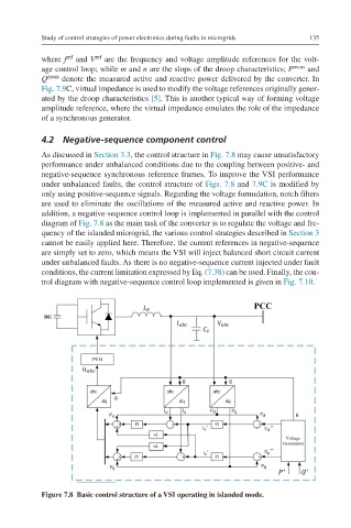
As discussed in Section 3.3, the control structure in Fig. 7.8 may cause unsatisfactory
performance under unbalanced conditions due to the coupling between positive- and
negative-sequence synchronous reference frames. To improve the VSI performance
under unbalanced faults, the control structure of Figs. 7.8 and 7.9C is modified by
only using positive-sequence signals. Regarding the voltage formulation, notch filters
are used to eliminate the oscillations of the measured active and reactive power. In
addition, a negative-sequence control loop is implemented in parallel with the control
diagram of Fig. 7.8 as the main task of the converter is to regulate the voltage and fre-
quency of the islanded microgrid, the various control strategies described in Section 3
cannot be easily applied here. Therefore, the current references in negative-sequence
are simply set to zero, which means the VSI will inject balanced short circuit current
under unbalanced faults. As there is no negative-sequence current injected under fault
conditions, the current limitation expressed by Eq. (7.38) can be used. Finally, the con-
trol diagram with negative-sequence control loop implemented is given in Fig. 7.10.
Figure 7.8 Basic control structure of a VSI operating in islanded mode.