
Page 154 - Hybrid-Renewable Energy Systems in Microgrids
P. 154
138 Hybrid-Renewable Energy Systems in Microgrids
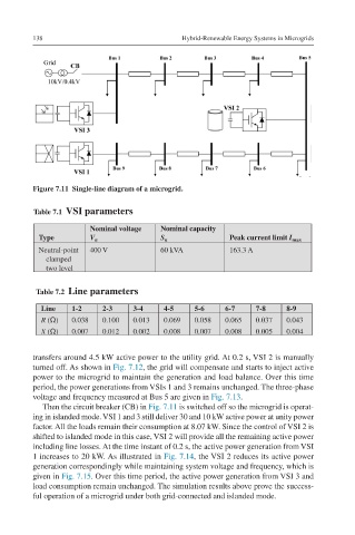
Figure 7.11 Single-line diagram of a microgrid.
Table 7.1 VSI parameters
Nominal voltage Nominal capacity
Type V n S n Peak current limit I max
Neutral-point 400 V 60 kVA 163.3 A
clamped
two level
Table 7.2 Line parameters
Line 1-2 2-3 3-4 4-5 5-6 6-7 7-8 8-9
R (Ω) 0.038 0.100 0.013 0.069 0.058 0.065 0.037 0.043
X (Ω) 0.007 0.012 0.002 0.008 0.007 0.008 0.005 0.004
transfers around 4.5 kW active power to the utility grid. At 0.2 s, VSI 2 is manually
turned off. As shown in Fig. 7.12, the grid will compensate and starts to inject active
power to the microgrid to maintain the generation and load balance. Over this time
period, the power generations from VSIs 1 and 3 remains unchanged. The three-phase
voltage and frequency measured at Bus 5 are given in Fig. 7.13.
Then the circuit breaker (CB) in Fig. 7.11 is switched off so the microgrid is operat-
ing in islanded mode. VSI 1 and 3 still deliver 30 and 10 kW active power at unity power
factor. All the loads remain their consumption at 8.07 kW. Since the control of VSI 2 is
shifted to islanded mode in this case, VSI 2 will provide all the remaining active power
including line losses. At the time instant of 0.2 s, the active power generation from VSI
1 increases to 20 kW. As illustrated in Fig. 7.14, the VSI 2 reduces its active power
generation correspondingly while maintaining system voltage and frequency, which is
given in Fig. 7.15. Over this time period, the active power generation from VSI 3 and
load consumption remain unchanged. The simulation results above prove the success-
ful operation of a microgrid under both grid-connected and islanded mode.