
Page 152 - Hybrid-Renewable Energy Systems in Microgrids
P. 152
136 Hybrid-Renewable Energy Systems in Microgrids
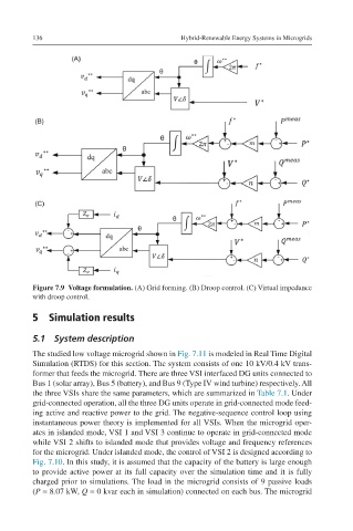
Figure 7.9 Voltage formulation. (A) Grid forming. (B) Droop control. (C) Virtual impedance
with droop control.
5 Simulation results
5.1 System description
The studied low voltage microgrid shown in Fig. 7.11 is modeled in Real Time Digital
Simulation (RTDS) for this section. The system consists of one 10 kV/0.4 kV trans-
former that feeds the microgrid. There are three VSI interfaced DG units connected to
Bus 1 (solar array), Bus 5 (battery), and Bus 9 (Type IV wind turbine) respectively. All
the three VSIs share the same parameters, which are summarized in Table 7.1. Under
grid-connected operation, all the three DG units operate in grid-connected mode feed-
ing active and reactive power to the grid. The negative-sequence control loop using
instantaneous power theory is implemented for all VSIs. When the microgrid oper-
ates in islanded mode, VSI 1 and VSI 3 continue to operate in grid-connected mode
while VSI 2 shifts to islanded mode that provides voltage and frequency references
for the microgrid. Under islanded mode, the control of VSI 2 is designed according to
Fig. 7.10. In this study, it is assumed that the capacity of the battery is large enough
to provide active power at its full capacity over the simulation time and it is fully
charged prior to simulations. The load in the microgrid consists of 9 passive loads
(P = 8.07 kW, Q = 0 kvar each in simulation) connected on each bus. The microgrid