
Page 157 - Hybrid-Renewable Energy Systems in Microgrids
P. 157
Study of control strategies of power electronics during faults in microgrids 141
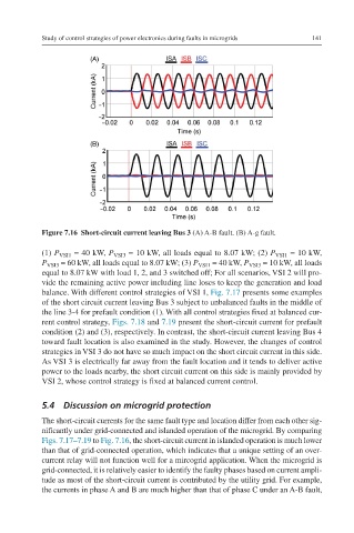
Figure 7.16 Short-circuit current leaving Bus 3 (A) A-B fault. (B) A-g fault.
(1) P VSI1 = 40 kW, P VSI3 = 10 kW, all loads equal to 8.07 kW; (2) P VSI1 = 10 kW,
P VSI3 = 60 kW, all loads equal to 8.07 kW; (3) P VSI1 = 40 kW, P VSI3 = 10 kW, all loads
equal to 8.07 kW with load 1, 2, and 3 switched off; For all scenarios, VSI 2 will pro-
vide the remaining active power including line loses to keep the generation and load
balance. With different control strategies of VSI 1, Fig. 7.17 presents some examples
of the short circuit current leaving Bus 3 subject to unbalanced faults in the middle of
the line 3-4 for prefault condition (1). With all control strategies fixed at balanced cur-
rent control strategy, Figs. 7.18 and 7.19 present the short-circuit current for prefault
condition (2) and (3), respectively. In contrast, the short-circuit current leaving Bus 4
toward fault location is also examined in the study. However, the changes of control
strategies in VSI 3 do not have so much impact on the short circuit current in this side.
As VSI 3 is electrically far away from the fault location and it tends to deliver active
power to the loads nearby, the short circuit current on this side is mainly provided by
VSI 2, whose control strategy is fixed at balanced current control.
5.4 Discussion on microgrid protection
The short-circuit currents for the same fault type and location differ from each other sig-
nificantly under grid-connected and islanded operation of the microgrid. By comparing
Figs. 7.17–7.19 to Fig. 7.16, the short-circuit current in islanded operation is much lower
than that of grid-connected operation, which indicates that a unique setting of an over-
current relay will not function well for a mircogrid application. When the microgrid is
grid-connected, it is relatively easier to identify the faulty phases based on current ampli-
tude as most of the short-circuit current is contributed by the utility grid. For example,
the currents in phase A and B are much higher than that of phase C under an A-B fault,