
Page 63 - Hybrid-Renewable Energy Systems in Microgrids
P. 63
Integrated renewable energy sources with droop control techniques-based microgrid operation 47
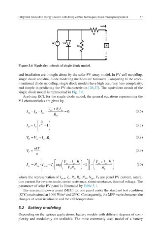
Figure 3.6 Equivalent circuit of single diode model. Iph−ID−Ipv−Vpv+RsIpvRsh=0
and irradiation are thought-about by the solar PV array model. In PV cell modeling,
single diode and dual diode modeling methods are followed. Comparing to the afore-
mentioned diode modeling, single diode models have high accuracy, less complexity,
and simple in predicting the PV characteristics [26,27]. The equivalent circuit of the
single diode model is represented in Fig. 3.6.
Applying KCL for the single diode model, the general equations representing the
V-I characteristics are given by,
V + R I
I − I − I − pv spv = 0 (3.6)
ph D pv
R sh
V D
I = I e V r −1 (3.7) ID=IoeVDVr−1
D o
V D = V pv + I . R s (3.8) VD=Vpv+Ipv.Rs
pv
nkT
V = (3.9) VT=nkTq
T
q
V + I . R V + I . R
I pv = N pp I pv n − I o exp pv pv s − −1 pv pv s (10) Ipv=NppIpv,n−IoexpVpv+Ipv
,
VN ss R p .RsVTNss−1−Vpv+Ipv.RsRp
T
where the representation of I pv,n , I o , R s , R p , N ss , N pp , V T are panel PV current, satura-
tion current for reverse mode, series resistance, shunt resistance, thermal voltage. The
parameter of solar PV panel is illustrated by Table 3.1.
The maximum power point (MPP) for one panel under the standard test condition
2
(STC) maintained at 1000 W/m and 25°C. Consequently, the MPP varies between the
changes of solar irradiance and the cell temperature.
5.2 Battery modeling
Depending on the various applications, battery models with different degrees of com-
plexity and modularity are available. The most commonly used model of a battery