
Page 68 - Hybrid-Renewable Energy Systems in Microgrids
P. 68
52 Hybrid-Renewable Energy Systems in Microgrids
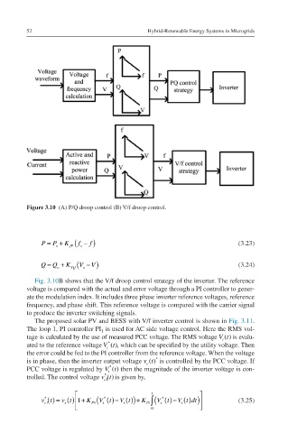
Figure 3.10 (A) P/Q droop control (B) V/f droop control.
P=Po+KfPfo−f P = P o + K fP ( f o − ) f (3.23)
Q=Qo+KVQVo−V Q = Q o + K VQ (V o −V ) (3.24)
Fig. 3.10B shows that the V/f droop control strategy of the inverter. The reference
voltage is compared with the actual and error voltage through a PI controller to gener-
ate the modulation index. It includes three phase inverter reference voltages, reference
frequency, and phase shift. This reference voltage is compared with the carrier signal
to produce the inverter switching signals.
The proposed solar PV and BESS with V/f inverter control is shown in Fig. 3.11.
The loop 1, PI controller PI 1 is used for AC side voltage control. Here the RMS vol-
Vt(t) tage is calculated by the use of measured PCC voltage. The RMS voltage Vt() is evalu-
t
*
Vt*(t) ated to the reference voltage Vt(), which can be specified by the utility voltage. Then
t
the error could be fed to the PI controller from the reference voltage. When the voltage
*
vc(t)* is in phase, then the inverter output voltage vt() is controlled by the PCC voltage. If
c
*
Vt*(t) PCC voltage is regulated by Vt() then the magnitude of the inverter voltage is con-
t
*
vc1*(t) trolled. The control voltage vt() is given by,
c1
t
*
*
*
()−Vt
() = vt 1
()−V t
vc1*t=vtt1+KP1Vt*t−Vtt+KI1∫0tVt*t−Vt vt t () + K P1 (V t t () ) + K I1 ∫ (Vt t ()dt ) (3.25)
t
c1
t
tdt 0 