
Page 70 - Hybrid-Renewable Energy Systems in Microgrids
P. 70
54 Hybrid-Renewable Energy Systems in Microgrids
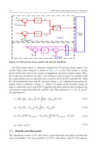
Figure 3.12 P/Q inverter droop control with solar PV and BESS.
The P/Q droop control is somewhat changed by V/f inverter droop control. The
inverter P/Q control diagram is shown in Fig. 3.12. In this P/Q control is mainly
based on the active and reactive power of magnitude and phase output voltage. Here,
two loops are considered. In loop 1, the reference reactive power is evaluated with
the actual reactive power, and then error could be fed to the PI controller PI . Then
1
vt the aforementioned terms and the terminal voltage v are multiplied and getting the
t
*
vc1* output values is reference voltage v , which is in phase of the terminal voltage. In
c1
*
α * loop 2, control the active power PI to generate the phase shift α and it balances the
2
1
1
*
*
*
*
α
vc1* *α *α* active power output from both AC and DC side. The equations of v , α , α and α
c1
1
2
1 2
are illustrated by,
t
*
( (Q
1)
vc1*=KP1Qref−Qactual+KI1 v c1 = K P1 ref −Q actual ) ) + K I1 ∫ (Q ref −Q actual ) dt + v t (3.29)
∫0tQref−Qactual dt+1)vt 0
t
*
α = K − P − P (3.30)
α *=KP2Pref−Pactual+KI2∫ 1 P2 ( P ref actual ) + K I 2 ∫ ( P ref actual ) dt
1
0tPref−Pactual dt 0
t
*
α *=KP31.02*PACmeasur α = K P3 (1.02* P ACmeasured − P DC ) + K I 3 ∫ (1.02* P AC measured − P DC ) dt (3.31)
2
2
ed−PDC+KI3∫0t1.02*PA- 0
Cmeasured−PDC dt
α*=α *+α */2
2
1
α ( α + α ) /2 (3.32)
*
*
*
=
2
1
7.1 Results and discussion
The simulation results of PV and battery grid-connected microgrid operation has
been shown below. The time period 0 s to 0.05 s, the battery, and PV load capacity