
Page 69 - Hybrid-Renewable Energy Systems in Microgrids
P. 69
Integrated renewable energy sources with droop control techniques-based microgrid operation 53
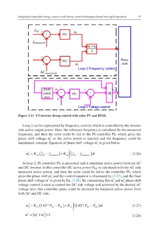
Figure 3.11 V/f inverter droop control with solar PV and BESS.
Loop 2 can be represented by frequency control, which is controlled by the inverter
side active output power. Here, the reference frequency is calculated by the measured
frequency, and then the error could be fed to the PI controller PI which gives the
2
*
phase shift voltage α so the active power is injected and the frequency could be α *
1
1
*
maintained constant. Equation of phase shift voltage α is given below. α *
1
1
t
*
α = K ( f − f ) + K ∫ ( f − f ) dt (3.26) α *=KP2fref−fmeasured+KI
1 P2 ref measured I 2 ref measured 1
0 2∫0tfref−fmeasured dt
In loop 2, PI controller PI is presented and it maintains active power between AC
3
and DC inverter. In this controller DC active power P is calculated with the AC side
DC
measured active power, and then the error could be fed to the controller PI which
3
*
gives the phase shift α and the control equation is illustrated by (3.27), and the final α 2 *
2
*
*
*
phase shift voltage α is given by Eq. (3.28). By considering this α and α phase shift α* 1 *
*
1
2
α α 2
voltage control is used to control the DC side voltage and achieved by the desired AC
voltage also, this controller gains could be declared the balanced active power from
both AC and DC side.
t
*
α = K P3 (1.02* P AC − P DC ) + K I 3 ∫ (1.02* P AC − P DC )dt (3.27) α *=KP31.02*PAC−PDC+K
2
2
0 I3∫0t1.02*PAC−PDC dt
α ( α + α ) /2
=
*
*
*
1 2 (3.28) α*=α *+α *
2
1