
Page 64 - Hybrid-Renewable Energy Systems in Microgrids
P. 64
48 Hybrid-Renewable Energy Systems in Microgrids
Table 3.1 Parameters of solar PV panel
Parameters Value
Rated voltage 18.65 V
Rated current 4.94 A
Short circuit current 5.24
Open circuit voltage 22.32
Series solar cells 36
Parallel solar cells 1
Rated power 92 W
containing constant resistance is connected in series with the ideal voltage supply.
In this model SoC is not necessary; it is only suitable for low voltage applications.
Another common model is thevenin battery model, which consists of internal resis-
tance connected in series with the parallel combination overvoltage capacitance and
resistance. In this model all the elements could be maintained constant and also the bat-
tery characteristics ought to be varied depending on the discharge rate and SoC [28].To
avoid battery complexity, generic dynamic battery model is proposed. Nowadays BESS
is most efficient one of all the electrochemical energy storage technologies present in
the market. In our work, lead acid battery storage bank is used. The main function of
this battery bank is at times when PV array does not generate the required voltage, the
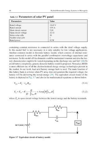
battery will be delivering the stored energy [29]. The equivalent circuit model of the
battery is depicted in Fig. 3.7 and also in the mathematical equations as shown below.
Vbatt=Eg−ibattRbatt V batt = E g − iR batt (3.11)
batt
∫ (
Q
Eg=Ego−KQQ−∫ibattdt+Ae E g = E go − K + Aexp B i batt dt ) (3.12)
xpB∫ibattdt Q − i dt
∫ batt
where E is open circuit voltage between the stored energy and the battery terminals.
g
Figure 3.7 Equivalent circuit of battery model.