
Page 49 - Hydrocarbon
P. 49
36 Exploration Methods and Techniques
seismic trace reflectivity series rock units
(spikes)
Figure 3.18 Deconvolution.
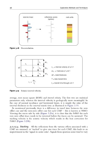
t dz
v 1 1
1
v = internal velocity of unit 1
dZ T t 2 dz 2 1
v
2
dz 1 = thickness of unit 1
t 3 dz 3
v dZ = total thickness
3
T = total transit time
dz 1
t =
1 v 1 t = transit time through unit 1
1
Figure 3.19 Seismic interval velocity.
average, root mean square (RMS) and interval velocity. The first two are statistical
parameters only, whereas the interval velocity is geologically more meaningful. In
the case of normal incidence and horizontal layers, it is simply the ratio of the
interval thickness to the interval transit time as illustrated in Figure 3.19.
As mentioned previously, there is a difference in travel time between the zero
offset case and the non-zero offset case for each CMP – this is known as NMO.
Viewing the traces side by side (Figure 3.20a), it is clear that the NMO for each
non-zero offset trace needs to be removed before the traces can be summed. The
stacking velocity is the seismic velocity which results in the best correction for
NMO (Figure 3.20b).
3.2.2.5.4. Stacking. All the reflections from the various offsets associated with a
CMP are summed, or ‘stacked’ to give one trace for each CMP; this leads to an
improvement in the ‘signal-to-noise ratio’. Signals from spurious noise tend to vary