
Page 50 - Hydrocarbon
P. 50
Exploration 37
between the different traces and will, therefore, get cancelled out or at least
suppressed. True geological signals from the different traces tend to be similar and
are thus boosted during the stacking process.
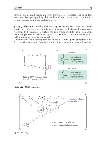
3.2.2.5.5. Migration. Ideally, after stacking the seismic data are in the correct
position and have the correct amplitudes. However, steeply dipping horizons cause
reflections to be recorded at surface positions which are different to their actual
subsurface position as shown in Figure 3.21. This also happens when large and
sudden variations occur in seismic velocity.
The incident wave coming from the source at S 1 hits a point at position a and
depth z and is reflected to the receiver at R 1 . In the case of horizontal reflectors the
a. b.
good stack
V 1 V 2 V 3 V 4 V 5 V 6
stacked trace
using correct
stacking velocity
bad stack
NMO
stacked trace
using incorrect
trace for CMP: increased travel stacking velocity
time with increased offset
Figure 3.20 NMO correction.
S 1 S 2 S 3 R 1 R 2 R 3
recorded reflector
re true reflector
i
re
i
c
re
i
b
z
a
θ app θapp = time dip of reflector
θ true θ true = apparent dip as recorded
Figure 3.21 Migration.