
Page 163 - Hydrocarbon Exploration and Production Second Edition
P. 163
150 Data Gathering
azimuthal resistivity transmitter for
(depth of investigation gamma ray wireless telemetry
measurement 12in. or less) detector and measurement
antenna
current
surface-adjustable
3/4° fixed
bent housing bent housing motor
stabilizer
and bearings inclination RPM
gravity toolface
Figure 6.37 Schlumberger geosteering tool with LWD.
OnTrak
BCPM
AutoTrak G3 pressure resistivity directional bi-directional
azimuthal gamma + image vibration & stick-slip communications
& power module
LithoTrak SoundTrak TesTrak
density + image porosity compressional & formation pressure
caliper shear acoustic & mobility
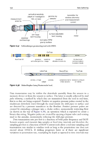
Figure 6.38 BakerHughes Inteq‘Pentacombo’tool.
Data transmission may be within the downhole assembly from the sensors to a
memory device or from the sensors to surface. The latter is usually achieved by mud
pulse telemetry, a method by which data are transmitted from the tool in real time,
that is as data are being acquired. Positive or negative pressure pulses created in the
mudstream downhole travel through the mud (inside the drill pipe) to surface and
are detected by a pressure transducer in the flowline. Positive pressure pulses are
created by extending a plunger into a choke orifice, momentarily restricting flow
(as shown in the top of Figure 6.38), an operation which is repeated to create a
binary data string. Negative pulses are created by opening a bypass valve and venting
mud to the annulus, momentarily reducing the drill pipe pressure.
Data transmission rate per foot is a function of both pulse frequency and ROP.
Sensors acquire and transmit data samples at fixed time intervals and therefore the
sampling per foot is a function of ROP. Current tools allow a real time sampling and
transmission rate similar to wireline tools as long as the penetration rate does not
exceed about 100 ft/h. If drilling progresses faster or if there are significant
variations in penetration rate, resampling by depth as opposed to time intervals may