
Page 283 - Hydrocarbon Exploration and Production Second Edition
P. 283
270 Oil and Gas Processing
Gas / Oil from Seperator Gas
Production to
7
Manifold Compression
2
1
V-101 LC
LC
INT
To Flare
4 3
5
V-102 LC
Stabilised
Produced 6 Crude to
Water to Storage
Treatment
P-101
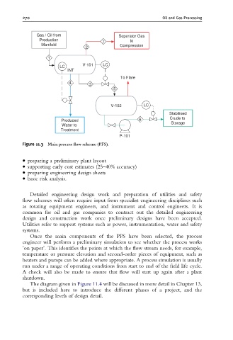
Figure 11.3 Main process £ow scheme (PFS).
preparing a preliminary plant layout
supporting early cost estimates (25–40% accuracy)
preparing engineering design sheets
basic risk analysis.
Detailed engineering design work and preparation of utilities and safety
flow schemes will often require input from specialist engineering disciplines such
as rotating equipment engineers, and instrument and control engineers. It is
common for oil and gas companies to contract out the detailed engineering
design and construction work once preliminary designs have been accepted.
Utilities refer to support systems such as power, instrumentation, water and safety
systems.
Once the main components of the PFS have been selected, the process
engineer will perform a preliminary simulation to see whether the process works
‘on paper’. This identifies the points at which the flow stream needs, for example,
temperature or pressure elevation and second-order pieces of equipment, such as
heaters and pumps can be added where appropriate. A process simulation is usually
run under a range of operating conditions from start to end of the field life cycle.
A check will also be made to ensure that flow will start up again after a plant
shutdown.
The diagram given in Figure 11.4 will be discussed in more detail in Chapter 13,
but is included here to introduce the different phases of a project, and the
corresponding levels of design detail.