
Page 288 - Hydrocarbon Exploration and Production Second Edition
P. 288
Surface Facilities 275
Typical residence times vary from some 3 minutes for a light crude to up to
20 minutes for very heavy crudes.
In summary, separator sizing is determined by three main factors:
gas velocity (to minimise mist carry over)
viscosity (residence time)
surge volume allowances (up to 50% over normal operating rates).
11.1.2.3. Separator types
Basic separator types can be characterised in two ways: firstly, by main function
(bulk or mist separation), and secondly, by orientation (either vertical or horizontal).
Knockout vessels are the most common form of basic separator. The vessel
contains no internals and demisting efficiency is poor. However, they perform well
in dirty service conditions (i.e. where sand, water and corrosive products are carried
in the well stream).
Demister separators are employed where liquid carry over is a problem. The
recovery of liquids is sometimes less important than the elimination of particles
prior to feeding a compression system.
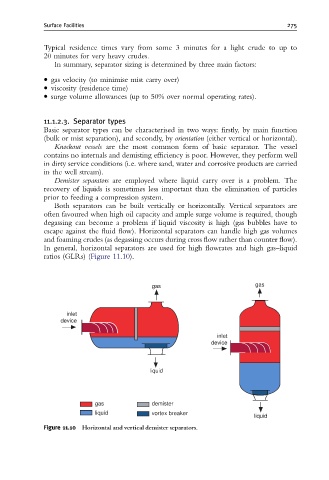
Both separators can be built vertically or horizontally. Vertical separators are
often favoured when high oil capacity and ample surge volume is required, though
degassing can become a problem if liquid viscosity is high (gas bubbles have to
escape against the fluid flow). Horizontal separators can handle high gas volumes
and foaming crudes (as degassing occurs during cross flow rather than counter flow).
In general, horizontal separators are used for high flowrates and high gas–liquid
ratios (GLRs) (Figure 11.10).
gas gas
inlet
device
inlet
device
liquid
gas demister
liquid vortex breaker
liquid
Figure 11.10 Horizontal and vertical demister separators.