
Page 261 - Hydrogeology Principles and Practice
P. 261
HYDC06 12/5/05 5:34 PM Page 244
244 Chapter Six
or
ρ
z = f z eq. 6.25
s ρ − ρ f
s f
−3
−3
which for ρ = 1000 kg m and ρ = 1025 kg m gives
f s
the Ghyben–Herzberg relation:
z = 40z eq. 6.26
s f
The Ghyben–Herzberg relation can also be applied to
confined aquifers by substituting the water table by
the potentiometric surface.
It can be seen from equation 6.26 that small vari-
ations in the freshwater head will have a large effect
on the position of the saltwater interface. If the water
table in an unconfined aquifer is lowered by 1 m, the
saltwater interface will rise 40 m. The freshwater–
saltwater equilibrium established requires that the
water table (or potentiometric surface) lies above sea
level and that it slopes downwards towards the sea.
Without these conditions, for example when ground-
water abstraction reduces the freshwater table in coastal
boreholes below sea level, seawater will advance
directly inland causing saline intrusion to occur.
It can be shown that where the groundwater flow
is nearly horizontal, the Ghyben–Herzberg relation
gives satisfactory results, except near the coastline
where vertical flow components are more pro-
nounced leading to errors in the position of the pre-
dicted saltwater interface. In most real situations, the
Ghyben–Herzberg relation underestimates the depth
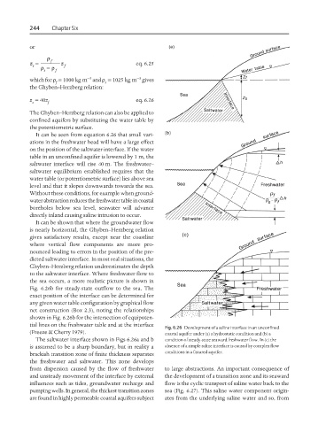
to the saltwater interface. Where freshwater flow to
the sea occurs, a more realistic picture is shown in
Fig. 6.26b for steady-state outflow to the sea. The
exact position of the interface can be determined for
any given water table configuration by graphical flow
net construction (Box 2.3), noting the relationships
shown in Fig. 6.26b for the intersection of equipoten-
tial lines on the freshwater table and at the interface
Fig. 6.26 Development of a saline interface in an unconfined
(Freeze & Cherry 1979). coastal aquifer under (a) a hydrostatic condition and (b) a
The saltwater interface shown in Figs 6.26a and b condition of steady-state seaward freshwater flow. In (c) the
is assumed to be a sharp boundary, but in reality a absence of a simple saline interface is caused by complex flow
brackish transition zone of finite thickness separates conditions in a fissured aquifer.
the freshwater and saltwater. This zone develops
from dispersion caused by the flow of freshwater to large abstractions. An important consequence of
and unsteady movement of the interface by external the development of a transition zone and its seaward
influences such as tides, groundwater recharge and flow is the cyclic transport of saline water back to the
pumping wells. In general, the thickest transition zones sea (Fig. 6.27). This saline water component origin-
are found in highly permeable coastal aquifers subject ates from the underlying saline water and so, from