
Page 118 - Improving Machinery Reliability
P. 118
90 Improving Machinery Reliability
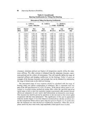
Table 3-1 (continued)
Bearing Coefficients for Tilting Pad Bearing
Dimensional Tilting Pad Bearing Coefficients
L = 1.875 in. D = 4.500 in. C = .00450 in.
Load = 438.0 Ibs = 2.50E - 06 REYNS
ECC. Kxx KYY cxx CYY HP loss
(dim) (Ibh) (Ibhn.) (Ib-s/in.) (Ib-s/in.) (hP)
.05 19748.2 3.058+06 3.088+06 1.62E+03 1.63E+03 6.16E+01
.IO 9744.4 1.528+06 1.58Et-06 1.64E-t-03 1.68E+03 I .50E+OI
.I5 6350.6 1.01 E+06 I.llE+06 1.668+03 1.758+03 6.43B+00
.20 4611.7 7.538+05 8.848+05 1.688+03 1.87E+03 3.42E+00
.25 3535.0 5.958+05 7.688+05 I .72E+03 2.038+03 2.03E+00
.30 2790.6 4.868+05 7.068+05 1.76E+ 03 2.25E+03 1.28E+00
.35 2237.0 4.058+05 6.78Et-05 1.808+03 2.548+03 8.39E-01
.40 1804.7 3.418+05 6.738+05 1.868+03 2.9481-03 5.5XE-01
.45 1455.3 2.88E+05 6.88E+05 1.928+03 3.498+03 3.728-01
.50 1166.3 2.42E+05 7.21E+05 1.988+03 4.24E+03 2.468-01
.55 923.9 2.02E+05 7.7281-05 2.06E+03 5.30E+03 I .6OE-Ol
.60 719.1 1.66E+05 8.458+05 2.14E+03 6.84E-t.03 1.018-01
.65 546.0 1.338+05 9.44E+05 2.22E+03 9.15E+03 6.14E-02
.70 400.7 1.03E+05 1.08E+06 2.32E+03 I .28E+04 3.538-02
.75 280.4 7.688+04 1.278+06 2.42E+03 1.88E+04 1.888-02
.so 183.2 5.338+04 1.55Ec06 2.54E+03 2.98E+04 8.988-03
.85 107.9 3.358+04 2.008+06 2.67E+ 03 5.378+04 3.67E-03
.90 53.7 1.788+04 2.988+06 2.818+03 1.228+05 1.2lE-03
clearance, minimum preload and highest oil temperature usually define the mini-
mum stiffness. The other extreme is obtained from the minimum clearance, maxi-
mum preload and the coldest oil temperature. This will typically define the range of
expected stiffness and damping coefficients for the bearings. Table 3-2 gives an
example of the bearing clearances and preloads that can be obtained by considering
the range of dimensions on the shaft and bearing.
The anticipated range of rotor response should be calculated with the range of
bearing values and various combinations of unbalance. This is important since one
part of the API specifications 617 (2.8.1.9) states: “If the lateral critical speed as cal-
culated or revealed during mechanical testing falls within the specified operating
speed range or fails to meet the separation margin requirements after practical design
efforts are exhausted, the unit vendor shall demonstrate an insensitive rotor design.
This insensitivity must be proven by operation on the test stand at the critical speed
in question with the rotor unbalanced.” The significance of this can be appreciated
from the results (Figure 3-5) of the balanced mechanical test and the sensitivity test
for the compressor whose critical speed map was given in Figure 3-2. It can be seen
that the balanced run data showed no troublesome resonances. When the out-of-
phase sensitivity tests were made, high amplitude critical speeds were excited.