
Page 115 - Improving Machinery Reliability
P. 115
Machinery Reliability Audits and Reviews 87
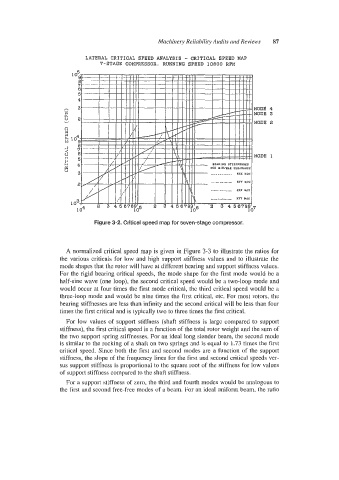
LATERAL CRITICAL SPEED ANALYSIS - CRITICAL SPEED MAP
?-STAGE COMPRESSOR, RUNNINQ SPEED 10800 RPM
Figure 3-2. Critical speed map for seven-stage compressor.
A normalized critical speed map is given in Figure 3-3 to illustrate the ratios for
the various criticals for low and high support stiffness values and to illustrate the
mode shapes that the rotor will have at different bearing and support stiffness values.
For the rigid bearing critical speeds, the mode shape for the first mode would be a
half-sine wave (one loop), the second critical speed would be a two-loop mode and
would occur at four times the first mode critical, the third critical speed would be a
three-loop mode and would be nine times the first critical, etc. For most rotors, the
bearing stiffnesses are less than infinity and the second critical will be less than four
times the first critical and is typically two to three times the first critical.
For low values of support stiffness (shaft stiffness is large compared to support
stiffness), the first critical speed is a function of the total rotor weight and the sum of
the two support spring stiffnesses. For an ideal long slender beam, the second mode
is similar to the rocking of a shaft on two springs and is equal to 1.73 times the first
critical speed. Since both the first and second modes are a function of the support
stiffness, the dope of the frequency lines for the first and second critical speeds ver-
sus support stiffness is proportional to the square root of the stiffness for low values
of support stiffness compared to the shaft stiffness.
For a support stiffness of zero, the third and fourth modes would be analogous to
the first and siecond free-free modes of a beam. For an ideal uniform beam, the ratio