
Page 114 - Improving Machinery Reliability
P. 114
86 Improviiig Machinery Reliability
Generally, each significant shaft diameter change is represented by one or more sta-
tions. A station is generally located at each added mass or inertia, at each bearing
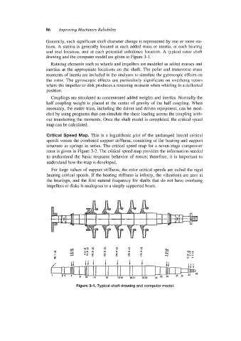
and seal location, and at each potential unbalance location. A typical rotor shaft
drawing and the computer model are given in Figure 3-1.
Rotating elements such as wheels and impellers are modeled as added masses and
inertias at the appropriate locations on the shaft. The polar and transverse mass
moments of inertia are included in the analyses to simulate the gyroscopic effects on
the rotor. The gyroscopic effects are particularly significant on overhung rotors
where the impeller or disk produces a restoring moment when whirling in a deflected
position.
Couplings are simulated as concentrated added weights and inertias. Normally the
half coupling weight is placed at the center of gravity of the half coupling. When
necessary, the entire train, including the driver and driven equipment, can be mod-
eled by using programs that can simulate the shear loading across the coupling with-
out transferring the moments. Once the shaft model is completed, the critical speed
map can be calculated.
Critical Speed Map. This is a logarithmic plot of the undamped lateral critical
speeds versus the combined support stiffness, consisting of the bearing and support
structure as springs in series. The critical speed map for a seven-stage compressor
rotor is given in Figure 3-2. The critical speed map provides the information needed
to understand the basic response behavior of rotors; therefore, it is important to
understand how the map is developed.
For large values of support stiffness, the rotor critical speeds are called the rigid
bearing critical speeds. If the bearing stiffness is infinity, the vibrations are zero at
the bearings, and the first natural frequency for shafts that do not have overhung
impellers or disks is analogous to a simply supported beam.
Figure 3-1. Typical shaft drawing and computer model.