
Page 126 - Improving Machinery Reliability
P. 126
98 Improving Muchinety Reliubility
UNBALANCE RESPONSE - GAS TWINE
S-SHOE TILT PIS, BEARINGS-WNbL CLEARANCE
UNBALAIICE AT STATION NO. 26 - COLRLING = 7.311 IHdZ AT 0 DE6.
VIBRATION AT STATION NO. 7 - DISC BR6
e see ieee me me me me ma 4eoe 4500 stwe ss~a 6880 6sec
ROTOR SPEED (RPW
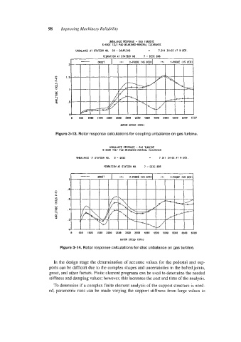
Figure 3-13. Rotor response calculations for coupling unbalance on gas turbine.
MALANCE RESPONSE - 6AS TURBINE
5-SHOE TILT PAD BEARINGS-NOHINU CLEARANCE
MALANCE :T STATION NO. 2 - DISC 7.311 IN-02 A1 0 DEG
VIBRATION AT SlATION NO. 7 - DISC BRS
e see 1000 1588 2880 2588 3808 3508 4888 4588 see8 5se~ mae 6588
ROTOR SPEED CRPH)
Figure 3-14. Rotor response calculations for disc unbalance on gas turbine.
In the design stage the determination of accurate values for the pedestal and sup-
ports can be difficult due to the complex shapes and uncertainties in the bolted joints,
grout, and other factors. Finite element programs can be used to determine the needed
stiffness and damping values; however, this increases the cost and time of the analysis.
To determine if a complex finite element analysis of the support structure is need-
ed, parametric runs can be made varying the support stiffness from large values to