
Page 132 - Improving Machinery Reliability
P. 132
104 Improving Machinery Reliability
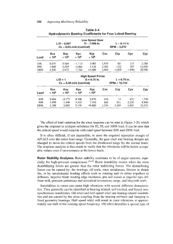
Table 3-4
Hydrodynamic Bearing Coefficients for Four Lobed Bearing
Low Speed Gear
LID = 0.867 D = 7.086 in. L = 6.14 in.
CL = 6.03 mils (nominal) RPM = 5,670
Kxx Kxy Kyx Kyy Cxx Cxy Cyx CYY
Load x106 x106 x106 x106
10% 0.075 0.564 -1.1 10 1.080 1,870 36 1 315 3,780
50% 1.040 0.559 -3.460 5.130 2,360 -322 297 12,000
100% 2.500 0.972 -7.760 12.400 3,880 -1,960 -1,890 28,900
High Speed Pinion
UD=l D = 6.75 in. L = 6.75 in.
CL = 5.38 mils (nominal) RPM = 10,742
Kxx Kxy Kyx Kyy Cxx Cxy Cyx CYY
Load x106 x106 xlOe x106
10% 0.464 -0.175 0.708 0.976 656 14 422 1,720
50% 2.090 1.440 3.410 7.310 868 811 2,250 8,960
100% 5.390 5.090 9.190 19.600 1,256 2,569 4,859 24,270
The effect of load variation for the rotor response can be seen in Figure 3-20, which
gives the response to midspan unbalance for 10,50, and 100% load. It can be seen that
the critical speed would coincide with rated speed between 50% and 100% load.
It is often difficult, if not impossible, to meet the required separation margin of
API 613 over the entire load range. Generally, the gear shaft and bearing designs are
changed to move the critical speeds from the disallowed range for the normal loads.
The response analysis is then made to verify that the vibrations will be below accept-
able values even if on resonance at the lower loads.
Rotor Stability Analyses. Rotor stability continues to be of major concern, espe-
cially for high-pressure compressor^.^^-'^ Rotor instability occurs when the rotor
destabilizing forces are greater than the rotor stabilizing forces. The destabilizing
forces can be caused by: the bearings, oil seals, rotor unbalances, friction in shrink
fits, or by aerodynamic loading effects such as rotating stall in either impellers or
diffusers, impeller blade loading edge incidence, jets and wakes at impeller tips, dif-
fuser stall, pressure pulsations and acoustical resonances, surge, and labyrinth seals.
Instabilities in rotors can cause high vibrations with several different characteris-
tics. They generally can be classified as bearing related, self-excited, and forced non-
synchronous instabilities. Oil whirl and half-speed whirl are bearing related instabili-
ties and are caused by the cross coupling from the bearing stiffness and damping in
fixed geometry bearings. Half-speed whirl will result in rotor vibrations at approxi-
mately one-half of the running speed frequency. Oil whirl describes a special type of