
Page 135 - Improving Machinery Reliability
P. 135
Machinery Reliubility Audits arid Reviews
.5 ‘.E 107
I
MAXIHUH
CL.
STABLE
F=F== ,
................. .................
MARGINAL
u
W a
8
-I
UNSTABLE
102 lo4 lo5
AE’RODYNAIIIC LOADING - LBAN
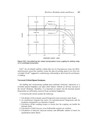
Figure 3-21. Calculated log dec versus aerodynamics cross coupling for stability analy-
sis of centrifugal compressor.
Kirk’’ has developed stability criteria that use the final pressure times the differ-
ential pressure across the machine versus the ratio of running speed to the first criti-
cal speed. StrohZ3 suggested a work/energy relationship to determine the aerodynam-
ic loading.
Torsional Critical Speed Analyses
All rotating and reciprocating systems have torsional vibrations. Operation on a
torsional natural frequency can cause shaft failures without an obvious increase in
the lateral vibrations. Therefore, it is important to ensure that all torsional natural
frequencies are sufficiently removed from excitation frequencies.
A torsional audit should include the following:
I. Calculation of the torsional natural frequencies and associated mode shapes.
2. An interference diagram that shows the torsional natural frequencies and the
excitation components as a function of speed.
3. Calculatiion of the coupling torques to ensure that the coupling can handle the
dynamic loads.
4. Calculatiion of shaft stresses, even if allowable margins are satisfied.
5. Calculation of transient torsional stresses and allowable number of starts for
synchronous motor drives.