
Page 231 - Improving Machinery Reliability
P. 231
202 Improving Machinery Reliability
Background: Serious failures of fan spokes (Le. central hub arms) and fan
blades have been attributed to inadequate weld procedures, insufficient design
margins of safety, or both.
5. Vibration cutout devices should incorporate velocity- or acceleration-based
solid-state circuitry, a built-in electronic delay circuit, and analog outputs to
allow continuous monitoring and trend analysis. The automatic shutdown fea-
ture of the vibration monitoring device should energize to trip.
Background: Some vibration cutout switches furnished by cooling tower
vendors are simple devices which have clearly demonstrated unsatisfactory ser-
vice life and have failed to actuate under emergency conditions. Fires and
severe mechanical damage at several locations have been attributed to faulty
vibration cutout devices.
6. At one process plant, cyclone fences were place around the fan stacks after the
first blade failure sprayed debris over a wide area of the unit. These fences
entrapped virtually all significant pieces of subsequent blade failures. Similar
fences should be placed around the fiberglass stacks of cooling tower installa-
tions when using extra-large or unproven blade designs.
Cooling Tower Fan Mechanical Test Example. With a low-frequency
accelerometer temporarily clamped to a point mid-span on the airfoil skin, each
blade is struck and the resulting frequency displayed on a digital frequency analyzer.
Observed values represent the blade static frequency f,,. These values are recorded
for later comparison with a “safe design” criterion.
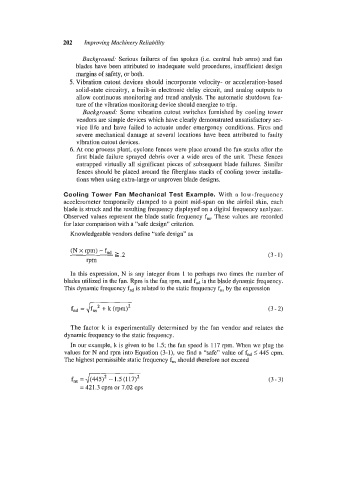
Knowledgeable vendors define “safe design” as
In this expression, N is any integer from I to perhaps two times the number of
blades utilized in the fan. Rpm is the fan rpm, and fnd is the blade dynamic frequency.
This dynamic frequency fnd is related to the static frequency f,, by the expression
The factor k is experimentally determined by the fan vendor and relates the
dynamic frequency to the static frequency.
In our example, k is given to be 1.5; the fan speed is 117 rpm. When we plug the
values for N and rpm into Equation (3-I), we find a “safe” value of fnd I445 cpm.
The highest permissible static frequency f,, should therefore not exceed
fn, = J(445)’ - 1.5 (1 17)’ (3 - 3)
= 421.3 cpm or 7.02 cps