
Page 233 - Improving Machinery Reliability
P. 233
204 Improving Machinery Reliability
The economic incentives of finding ways of salvaging major rotating equipment
shafts are illustrated on a steam-turbine shaft originally rated to transmit 17,600 HP
maximum at 6,400 rpm. Several years ago, a turbine uprate to 19,600 HP was autho-
rized. It was determined that the required change-out of stationary steam-path com-
ponents would cost around $60,000, but a combined replacement cost of about
$500,000 was quoted for the main and spare rotor shafts. A rigorous calculation of
shaft stresses showed the shaft factor of safety to be greater at 19,600 HP using a
diaphragm coupling than at 17,600 HP using a conventional gear coupling!
Maximum Shaft Stress Calculated
Efforts to determine whether or not rotating equipment power uprates require shaft
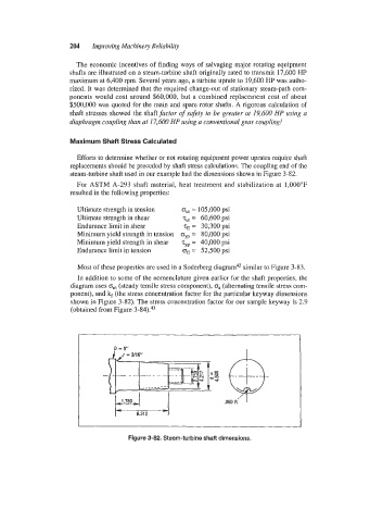
replacements should be preceded by shaft stress calculations. The coupling end of the
steam-turbine shaft used in our example had the dimensions shown in Figure 3-82.
For ASTM A-293 shaft material, heat treatment and stabilization at 1,000"F
resulted in the following properties:
Ultimate strength in tension but = 105,000 psi
Ultimate strength in shear tUt 60,600 psi
=
Endurance limit in shear tE = 30,300 psi
Minimum yield strength in tension oyp = 80,000 psi
Minimum yield strength in shear typ 40,000 psi
=
Endurance limit in tension 08 = 52,500 psi
Most of these properties are used in a Soderberg diagram4* similar to Figure 3-83.
In addition to some of the nomenclature given earlier for the shaft properties, the
diagram uses G,,, (steady tensile stress component), O~ (alternating tensile stress com-
ponent), and kf (the stress concentration factor for the particular keyway dimensions
shown in Figure 3-82). The stress concentration factor for our sample keyway is 2.9
(obtained from Figure 3-84).43
Figure 3-82. Steam-turbine shaft dimensions.