
Page 234 - Improving Machinery Reliability
P. 234
Machinery Reliability Audits and Reviews 205
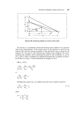
Figure 3-83. Soderberg diagram for steam-turbine shaft.
The line BIAl considered to define the limiting stress condition for a specimen
is
with stress concentrations. If the steady stress on the specimen is given by the
abscissa OD, then the limiting amplitude of the alternating stress is given by the
ordinate DC, and point C will represent the limiting stress condition. The corre-
sponding sa€e condition will be represented by point F with coordinates om and oa
(or T,,, and x8). These coordinates are obtained by dividing the coordinates of point C
by the factor of safety n. From the similarity of triangles we have:
Dividing this equation by n, we obtain for the safe stress condition (point F):
(3, +-=- Om 1
(3 - 4)
OEIkf Gyp
where
1
n=
kf-+L
Ga
(J
GYP