
Page 240 - Improving Machinery Reliability
P. 240
Machinery Reliability Audits and Reviews 211
-
Ga (diaphragm coupling) - Mtotal (diaphragm coupling)
o,(gear coupling) (gear coupling)
(1,095) (7,026)
Ga (diaphragm coupling) = = 122 psi
64,435
The mean tensile stress acting on the cross-sectional area of a diaphragm-cou-
pling-equipped shaft depends on how far the diaphragm is displaced axially from its
neutral rest position, and on the axial spring rate of the diaphragm. Assuming the
diaphragm of this sample case was displaced by its maximum permissible distance
of 0.100 in., it would exert a force of 1,950 lbs on the shaft cross-sectional area."4
This would cause a mean stress
1,950
om=-=-- 1,950 - 125 psi
nC2 n(2.25)2
Shaft Factor of Safety Evaluated
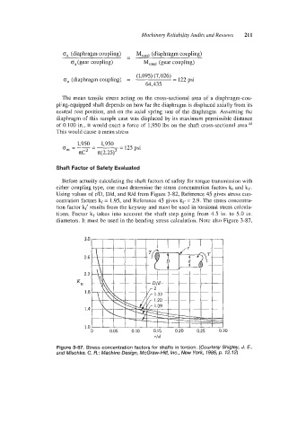
Before actually calculating the shaft factors of safety for torque transmission with
either coupling type, one must determine the stress concentration Factors kf and kf,.
Using values of r/D, D/d, and R/d from Figure 3-82, Reference 45 gives stress con-
centration factors kf = 1.95, and Reference 43 gives kf, = 2.9. The stress concentra-
tion factor k( results from the keyway and must be used in torsional stress calcula-
tions. Factor k, takes into account the shaft step going from 4.5 in. to 5.0 in.
diameters. It must be used in the bending stress calculation. Note also Figure 3-87,
0 0.05 0.10 0.15 0.20 0.25 0.30
rid
Figure 3-87. Stress concentration factors for shafts in torsion. (Courtesy Shigley, J. E.,
and Mischke, C. R.; Machine Design, McGraw-Hill, Inc., New York, 1986, p. 12.72)