
Page 431 - Improving Machinery Reliability
P. 431
Maiiztenance for Continued Reliability 395
38 M Elliott Compressor
Re-sealing of Casing Joint
Contractors:
A: Beta Maintenance And Machining Co.
Manpower (I I Supervisor, 5 Millwrights, 1 Days.
(2) I Supervisor, 3 Millwrights, h Days.
(3) Total Manhours = 282
B: McRae Field Machining Services, Inc.
M;nipower (I ) 2 Field Service Technicians
(2) Total Manhours = 16
Kcmarks:
1 . No tcnusual problems encountered. All tiincs representative of hiniilar niachinery.
2. On future jobs, iillo~ contingency of 24 hwrs lor possible prohlciiih with overhc;itl criincs
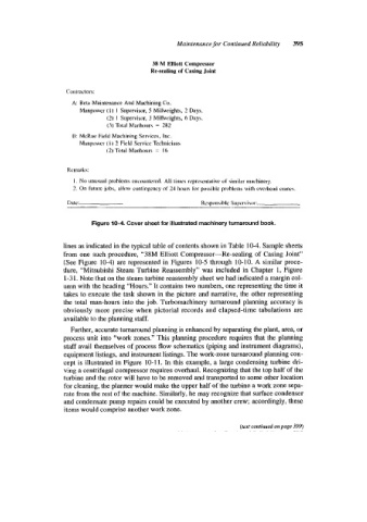
Figure 10-4. Cover sheet for illustrated machinery turnaround book.
lines as indicated in the typical table of contents shown in Table 10-4. Sample sheets
from one such procedure, “38M Elliott Compressor-Re-sealing of Casing Joint”
(See Figure 10-4) are represented in Figures 10-5 through 10-10. A similar proce-
dure, “Mitsubishi Steam Turbine Reassembly” was included in Chapter I, Figure
1-3 1. Note that on the steam turbine reassembly sheet we had indicated a margin col-
umn with the heading “Hours.” It contains two numbers, one representing the time it
takes to execute the task shown in the picture and narrative, the other representing
the total man-hours into the job. Turbomachinery turnaround planning accuracy is
obviously more precise when pictorial records and elapsed-time tabulations are
available to the planning staff.
Further, accurate turnaround planning is enhanced by separating the plant, area, or
process unit into “work zones.” This planning procedure requires that the planning
staff avail themselves of process flow schematics (piping and instrument diagrams),
equipment listings, and instrument listings. The work-zone turnaround planning con-
cept is illustrated in Figure 10-11. In this example, a large condensing turbine dri-
ving a centrifugal compressor requires overhaul. Recognizing that the top half of the
turbine and the rotor will have to be removed and transported to some other location
for cleaning, the planner would make the upper half of the turbine a work zone sepa-
rate from the rest of the machine. Similarly, he may recognize that surface condenser
and condensate pump repairs could be executed by another crew; accordingly, these
items would comprise another work zone.
(text corttinued 011 page 399)