
Page 99 - Improving Machinery Reliability
P. 99
Vendor Selection and Bid Conditioning 71
dicularity and seal setting accuracy are more difficult to achieve with the clamping
method indicated as execution G in Figure 2-8, which requires very careful adjust-
ment of cap screws inserted through the collar.
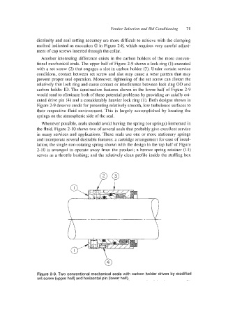
Another interesting difference exists in the carbon holders of the more conven-
tional mechanical seals. The upper half of Figure 2-9 shows a lock ring (1) executed
with a set screw (2) that engages a slot in carbon holder (3). Under certain service
conditions, contact between set screw and slot may cause a wear pattern that may
prevent proper seal operation. Moreover, tightening of the set screw can distort the
relatively thin lock ring and cause contact or interference between lock ring OD and
carbon holder ID. The construction features shown in the lower half of Figure 2-9
would tend to eliminate both of these potential problems by providing an axially ori-
ented drive pin (4) and a considerably heavier lock ring (1). Both designs shown in
Figure 2-9 deserve credit for presenting relatively smooth, low turbulence surfaces to
their respective fluid environment. This is largely accomplished by locating the
springs on the atmospheric side of the seal.
Whenever possible, seals should avoid having the spring (or springs) immersed in
the fluid. Figure 2-10 shows two of several seals that probably give excellent service
in many services and applications. These seals use one or more stationary springs
and incorporate several desirable features: a cartridge arrangement for ease of instal-
lation; the single non-rotating spring shown with the design in the top half of Figure
2-10 is arranged to operate away from the product; a bronze spring retainer (1 1)
serves as a throttle bushing; and the relatively clean profile inside the stuffing box
Figure 2-9. Two conventional mechanical seals with carbon holder driven by modified
set screw (upper half) and horizontal pin (lower half).