
Page 208 - Industrial Cutting of Textile Materials
P. 208
Fusing of cut textile components 195
12.3.1.2 Press with a vertically-lifting surface
This type of press ensures higher productivity as they are usually equipped with two
frames (also called a shuttle table/surfaces) for loading and unloading components.
Whilst one frame is fusing components, the other remains out of the heating zone and
can be loaded or unloaded (see Fig. 12.4).
A press consists of the following:
A heating zone with two work surfaces, where either the upper or the lower surface is mov-
●
able and heated whilst the other is fixed and unheated.
Two movable frames for loading and unloading components that are equipped with detach-
●
able screens with flaps to ensure the consistent positioning of the face fabric and interlining
components.
Methodology: Whilst one frame (3) containing components is fused in the heating
zone of the press, the operator unloads the previously fused components from the other
frame (1), loads the next set of components, and prepares them for the fusing process. As
the fusing process ends, the frame (3) with the fused components is taken out of the heat-
ing zone, and the newly loaded frame (1) is pulled into the heating zone (see Fig. 12.4).
The frames of a press may also be placed on both sides of the heating zone (see
Fig. 12.5). The press then has to be operated by two workers. Whilst one frame is in
the heating zone, the other is unloaded and reloaded in preparation for the next fusing
process. There is a third type of press with a vertical-lifting surface that makes a rotating
movement. This is operated by one worker, and the second frame is used only as a cool-
ing zone (Fig. 12.6). All types of flat (discontinuous) fusing presses use a timer to con-
trol the required fusing time. The temperature is electronically controlled up to 200°C.
1
2
3
4
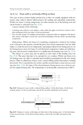
Fig. 12.4 Schema of a press with a vertical-lifting surface: (1) the first frame, (2) the fixed
worked surface, (3) the second frame, and (4) the movable and heated work surface.
4
1 2
3
Fig. 12.5 Schema of a press with frames on both sides of the heating zone: (1) the first frame,
(2) the second frame, (3) the fixed worked surface, and (4) the movable and heated work
surface.