
Page 226 - Industrial Power Engineering and Applications Handbook
P. 226
8/206 Industrial Power Engineering and Applications Handbook
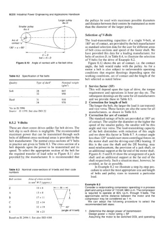
Larger pulley the pulleys be used with maximum possible diameters
dia D and distance between their centres be maintained as more
than the diameter of the larger pulley.
Selection of V-Belts
The load-transmitting capacities of a single V-belt, at
180" arc of contact, are provided by the belt manufacturer
as standard selection data for the user for different areas
of belt cross-sections and speed of the faster shaft. We
-C- have provided this data for a leading manufacturer, for
C>D belts of section D, in Table 8.4, to illustrate the selection
but c d+ D
of V-belts for the drive of Example 8.2.
Figure 8.10 Angle of contact with a flat-belt drive Figure 8.12 shows the arc of contact, i.e. the contact
angle, the belt would make with the pulley. As for a
motor a belt is also subject to unfavourable operating
conditions that require deratings depending upon the
Table 8.2 Specification of flat belts working conditions, arc of contact and the length of the
belt selected as noted below:
Quality Type of ducka Nominal weight
(glm2) 1 Service factor (SF)
This will depend upon the type of drive, the torque
Soft 28 845 requirement and operations in hour per day etc. The
32 950
subsequent deratings are the same for all manufacturers
Hard 31 910 and we provide these in Table 8.5.
34 970 2 Correction for length of belt
The longer the belt, the larger the load it can transmit
aAs in IS 5996 and vice versa. These factors are also the same for all
Source IS 1370. See also IS0 22 manufacturers, as shown in Table 8.6.
3 Correction for arc of contact
The standard ratings of belts are provided at 180" arc
8.5.2 V-Belts of contact. The smaller the diameter or the higher the
speed of the smaller pulley, the smaller will be this
These are short centre drives unlike flat belt drives. The angle and vice versa. The load-transmitting capacity
belt slip in such drives is negligible. The recommended of the belt diminishes with reduction of this angle
maximum power that can be transmitted through such and we show this factor in Table 8.7. A contact angle
belts of different cross-sectional areas is provided by the less than 120" would exert more centrifugal forces on
belt manufacturer. The normal cross-sections of V belts the motor shaft and the driving-end (DE) bearing. If
in practice are given in Table 8.3. The cross-section of a this is the case the shaft and the DE bearing, may
belt depends upon the power to be transmitted and its need reinforcement, the provision of a jack shaft, or
speed. To select the appropriate section of the belt for an additional support at the far end of the motor shaft.
the required transfer of load refer to Figure 8.11 also Figures 8.15 and 8.16 show the arrangement of a jack
provided by the manufacturer. It is recommended that shaft and an additional support at the far end of the
shaft respectively. Such a situation must, however, be
avoided, as far as possible.
In Example 8.2 we illustrate a step-by-step pro-
Table 8.3 Nominal cross-sections of V-belts and their code cedure to select the most appropriate size and length
numbers of belts and pulley sizes to transmit a particular
load.
Belt section Area of cross-section
in mm2 W.T (approx.)
Example 8.2
Consider a reciprocating compressor operating in a process
plant and using a motor of 110 kW, 980 r.p.m. The compressor
is required to operate at 825 r.p.m. through V-belts. The
approximate centre distance between the motor and the
compressor may be considered as 1 m.
\ I We can adopt the following procedure to select the
22 x14 \ I
recommended belt sizes:
32 x 19 40'
(angle of V-belt)
38 x23 1 Determine the design power of transmission
Design power = motor rating x SF
Based on IS 2494-1: See also IS0 4184 Assuming the motor to be switched DOL and operating