
Page 221 - Industrial Power Engineering and Applications Handbook
P. 221
Transmission of load and suitability of bearings 8/201
pumps, coal mill drives, conveyors, pulverizers and The couplings can be designed to develop torques
wagon tipplers. even higher than the Tpo of the motor. They can thus
Docks and harbours Material handling, mining, be made compatible for transmitting loads up to the
railway traction, process and chemical plants. optimum capacity of the motor and sustaining abnormal
load conditions without stalling or damage.
Most of these applications are heavy inertia loads and Basically a variable drive fluid coupling is a tailor-
require a light load start. The use of such variable drives made clutch to suit a specific load duty for more
can save energy. accurate application.
They are suitable for stepless speed variation and can
be controlled through speed, torque, temperature or
Advantages of variable-speed fluid couplings flow of a process. They can also be programmed for
any sequence of operation.
1 It is possible to switch the motor at no load by selecting Conventional throttling or damper control of flow is
a variable-speed fluid coupling. The oil need not be waste of energy. The use of such couplings can vary
prefilled which can be varied at site during operation speed through oil control, relieve strain on the system
as required. and save on the energy consumption.
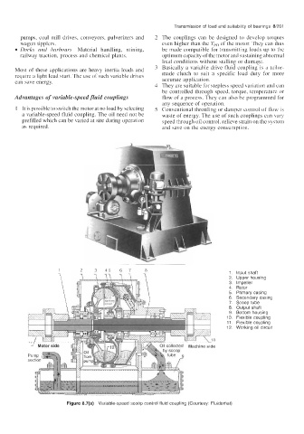
1. Input shaft
2. Upper housing
3. Impeller
4. Rotor
5. Primary casing
6. Secondary casing
7. Scoop tube
8. Output shaft
9. Bottom housing
10. Flexible coupling
11. Flexible coupling
12. Working oil circuit
Figure 8.7(a) Variable-speed scoop control fluid coupling (Courtesy: Fluidomat)