
Page 220 - Industrial Power Engineering and Applications Handbook
P. 220
8/200 Industrial Power Engineering and Applications Handbook
Figure 8.5 Constant filled fluid couplings (Courtesy: Pembril Fluid Drives)
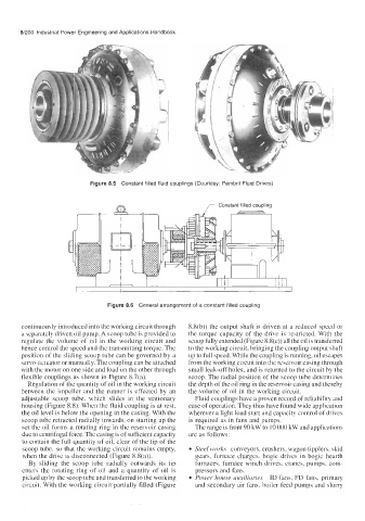
Figure 8.6 General arrangement of a constant filled coupling
continuously introduced into the working circuit through 8.8(b)) the output shaft is driven at a reduced speed or
a separately driven oil pump. A scoop tube is provided to the torque capacity of the drive is restricted. With the
regulate the volume of oil in the working circuit and scoop fully extended (Figure 8.8(c)) all the oil is transferred
hence control the speed and the transmitting torque. The to the working circuit, bringing the coupling output shaft
position of the sliding scoop tube can be governed by a up to full speed. While the coupling is running, oil escapes
servo-actuator or manually. The coupling can be attached from the working circuit into the reservoir casing through
with the motor on one side and load on the other through small leak-off holes, and is returned to the circuit by the
flexible couplings as shown in Figure 8.7(a). scoop. The radial position of the scoop tube determines
Regulation of the quantity of oil in the working circuit the depth of the oil ring in the reservoir casing and thereby
between the impeller and the runner is effected by an the volume of oil in the working circuit.
adjustable scoop tube, which slides in the stationary Fluid couplings have a proven record of reliability and
housing (Figure 8.8). When the fluid coupling is at rest, ease of operation. They thus have found wide application
the oil level is below the opening in the casing. With the wherever a light load start and capacity control of drives
scoop tube retracted radially inwards, on starting up the is required as in fans and pumps.
set the oil forms a rotating ring in the reservoir casing The range is from 90 kW to 10 000 kW and applications
due to centrifugal force. The casing is of sufficient capacity are as follows:
to contain the full quantity of oil, clear of the tip of the
scoop tube, so that the working circuit remains empty, Steel works conveyors, crushers, wagon tipplers, skid
when the drive is disconnected (Figure 8.8(a)). gears, furnace charges, bogie drives in bogie hearth
By sliding the scoop tube radially outwards its tip furnaces, furnace winch drives, cranes, pumps, com-
enters the rotating ring of oil and a quantity of oil is pressors and fans.
picked up by the scoop tube and transferred to the working Power house auxiliaries ID fans, FD fans, primary
circuit. With the working circuit partially filled (Figure and secondary air fans, boiler feed pumps and slurry