
Page 219 - Industrial Power Engineering and Applications Handbook
P. 219
Transmission of load and suitability of bearings 8/199
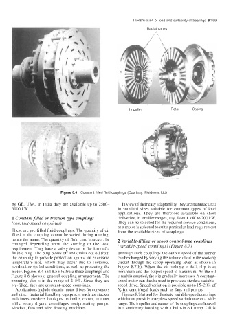
Radial vanes
lmoeller Rotor Casing
Figure 8.4 Constant filled fluid couplings (Courtesy: Fluidomat Ltd)
by GE, USA. In India they are available up to 2500- In view of their easy adaptability, they are manufactured
3000 kW. in standard sizes suitable for common types of load
applications. They are therefore available on short
1 Constant filled or traction type couplings deliveries, in smaller ranges, say, from 1 kW to 200 kW.
(constant-speed couplings) They can be selected for the required service conditions,
as a motor is selected to suit a particular load requirement
These are pre-filled fluid couplings. The quantity of oil from the available sizes of couplings.
filled in the coupling cannot be varied during running,
hence the name. The quantity of fluid can, however, be 2 Variable-filling or scoop control-type couplings
changed depending upon the starting or the load (variable-speed couplings) (Figure 8.7)
requirement. They have a safety device in the form of a
fusible plug. The plug blows off and drains out oil from Through such couplings the output speed of the runner
the coupling to provide protection against an excessive can be changed by varying the volume of oil in the working
temperature rise, which may occur due to sustained circuit through the scoop operating lever, as shown in
overload or stalled conditions, as well as protecting the Figure 8.7(b). When the oil volume is full, slip is at
motor. Figures 8.4 and 8.5 illustrate these couplings and minimum and the output speed is maximum. As the oil
Figure 8.6 shows a general coupling arrangement. The circuit is emptied, the slip gradually increases. A constant-
operating slip is in the range of 2-5%. Since they are speed motor can thus be used to provide a stepless variable-
pre-filled, they are constant-speed couplings. speed drive. Speed variation is possible up to 15-20% of
Applications include electric motor drives for conveyors N, for centrifugal loads such as fans and pumps.
and other material handling equipment such as stacker Figures 8.7(a) and (b) illustrate variable-speed couplings
reclaimers, crushers, haulages, ball mills, cranes, hammer which can provide a stepless speed variation over a wide
mills, rotary dryers, centrifuges, reciprocating pumps, range. The impeller and runner of the couplings are housed
winches, fans and wire drawing machines. in a stationary housing with a built-in oil sump. Oil is